Toyota Tacoma (2015-2018) Service Manual: Removal
REMOVAL
CAUTION / NOTICE / HINT
HINT:
If the bumper is damaged, there is a possibility that the installation area of the blind spot monitor sensor may be deformed and the blind spot monitor system may not operate correctly, so visually inspect the blind spot monitor sensor installation area (frame, stud bolt) to make sure it is not dented or bent.
Click here .gif)
If the visual inspection finds a problem, check the installation condition of the blind spot monitor sensor, and adjust the installation position of the blind spot monitor sensor as necessary.
PROCEDURE
1. REMOVE NO. 1 RECEIVER HITCH ATTACHMENT REINFORCEMENT
|
(a) Remove the 8 bolts. |
|
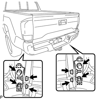
(b) Disengage the 4 guides to remove the 2 No. 1 receiver hitch attachment reinforcements.
2. REMOVE REAR BUMPER ASSEMBLY
|
(a) Disconnect the 3 connectors. |
|
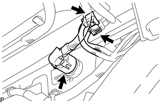
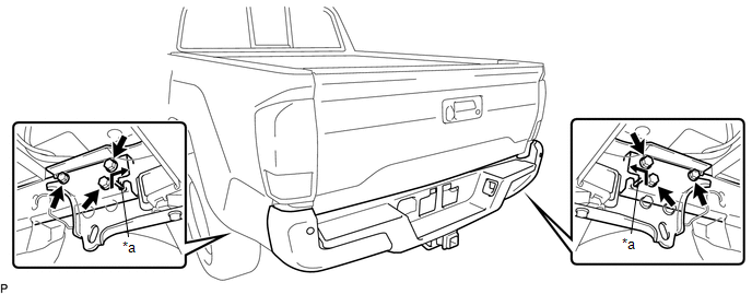
(b) Using an engine lifter or equivalent, remove the 6 bolts.
 Text in Illustration
|
*a |
Pin |
- |
- |
(c) Disengage the 2 pins to remove the rear bumper assembly as shown in the illustration.
NOTICE:
- Using plate lift attachments or equivalent, set the rear bumper assembly on a flat surface.
- Be sure to perform the operation with 2 persons or more.
- Be careful not to damage the rear bumper assembly.
 Components
COMPONENTS
ILLUSTRATION
ILLUSTRATION
ILLUSTRATION
ILLUSTRATION
...
 Disassembly
DISASSEMBLY
PROCEDURE
1. REMOVE CONNECTOR COVER
(a) Disengage the 2 clips to remove the connector cover.
2. REMOVE REAR BUMPER PAD SUB-ASSEMBLY ...
Other materials:
On-vehicle Inspection
ON-VEHICLE INSPECTION
PROCEDURE
1. INSPECT COOLER CONDENSER ASSEMBLY
(a) If the fins of the cooler condenser assembly are dirty, clean them with water
and dry them with compressed air.
NOTICE:
Do not damage the fins of the condenser assembly.
(b) If the fins of the cooler condenser assembly ...
Problem Symptoms Table
PROBLEM SYMPTOMS TABLE
HINT:
Use the table below to help determine the cause of the problem symptom.
The potential causes of the symptoms are listed in order of probability
in the "Suspected Area" column of the table. Check each symptom by checking
the suspected areas ...
Radar Cruise Control Presence Determination Malfunction (Engine / HV) (C1A52)
DESCRIPTION
DTC C1A52 is stored when the ECM cannot recognize the millimeter wave radar sensor
assembly.
DTC No.
Detection Item
DTC Detection Condition
Trouble Area
MIL
C1A52
Radar Cruise Control Presence Determin ...
