Toyota Tacoma (2015-2018) Service Manual: Components
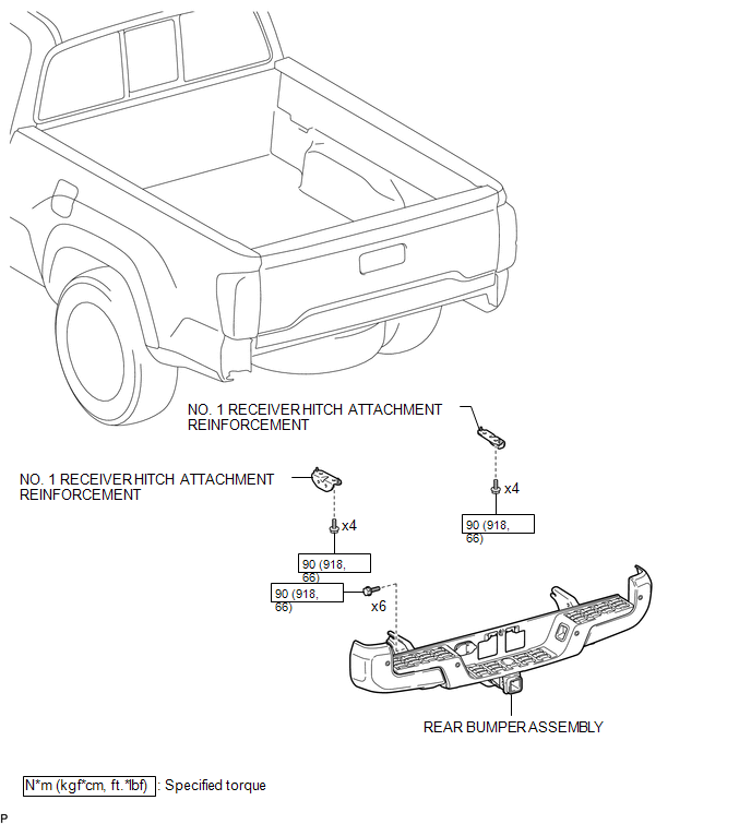
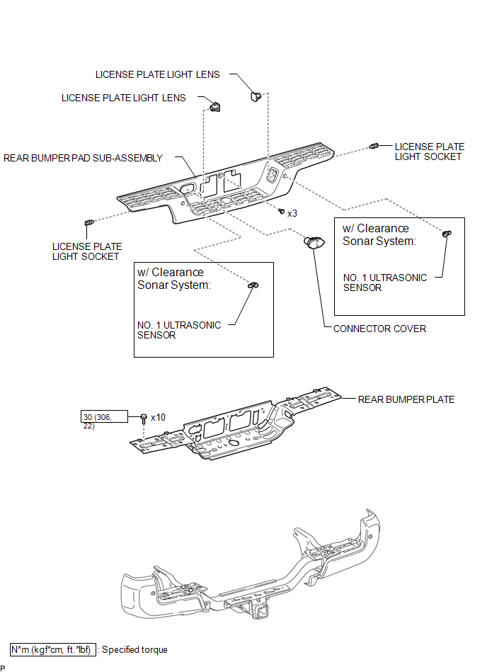
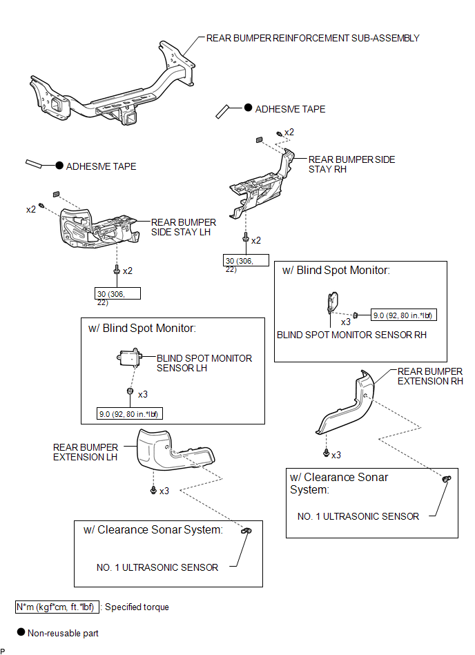
COMPONENTS
ILLUSTRATION
ILLUSTRATION
ILLUSTRATION
ILLUSTRATION

 Removal
REMOVAL
CAUTION / NOTICE / HINT
HINT:
If the bumper is damaged, there is a possibility that the installation area of
the blind spot monitor sensor may be deformed and the blind spot monitor syste ...
Other materials:
Terminals Of Ecu
TERMINALS OF ECU
1. CHECK SLIDING ROOF ECU (SLIDING ROOF DRIVE GEAR SUB-ASSEMBLY)
(a) Disconnect the S50 sliding roof ECU (sliding roof drive gear sub-assembly)
connector.
(b) Measure the resistance and voltage according to the value(s) in the table
below.
HINT:
Measure the values on the ...
Stop Light Relay Circuit (C1A4B)
DESCRIPTION
The skid control ECU (master cylinder solenoid)*1 or skid control ECU (brake
actuator assembly)*2 sends a stop light operation request signal to the stop light
relay (stop light switch assembly). If the skid control ECU (master cylinder solenoid)*1
or skid control ECU (brake actua ...
Diagnosis System
DIAGNOSIS SYSTEM
1. DESCRIPTION
(a) When troubleshooting a vehicle with a diagnosis system, the only difference
from the usual troubleshooting procedure is connecting the Techstream to the vehicle
and reading various data output from the clearance warning ECU assembly.
The clearance warning E ...
