Toyota Tacoma (2015-2018) Service Manual: Removal
REMOVAL
CAUTION / NOTICE / HINT
HINT:
- Use the same procedure for the RH side and LH side.
- The following procedure is for the LH side.
PROCEDURE
1. PRECAUTION
NOTICE:
After turning the ignition switch off, waiting time may be required before disconnecting the cable from the negative (-) battery terminal. Therefore, make sure to read the disconnecting the cable from the negative (-) battery terminal notices before proceeding with work.
Click here .gif)
2. DISCONNECT CABLE FROM NEGATIVE BATTERY TERMINAL
NOTICE:
When disconnecting the cable, some systems need to be initialized after the cable is reconnected.
Click here
3. REMOVE OUTER REAR VIEW MIRROR ASSEMBLY
Click here
4. REMOVE FRONT DOOR INSIDE HANDLE SUB-ASSEMBLY
Click here
5. REMOVE NO. 1 DOOR TRIM BRACKET
Click here
6. REMOVE FRONT DOOR SERVICE HOLE COVER
Click here
7. REMOVE NO. 2 FRONT DOOR SERVICE HOLE COVER
Click here
8. REMOVE FRONT DOOR GLASS SUB-ASSEMBLY
Click here
9. REMOVE FRONT DOOR GLASS OUTER WEATHERSTRIP ASSEMBLY
|
(a) Put protective tape around the front door glass outer weatherstrip assembly. |
|
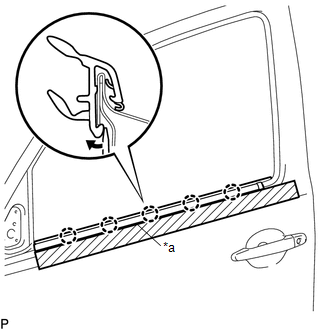
(b) Using a screwdriver, disengage the 5 claws to remove the front door glass outer weatherstrip assembly.
 Components
COMPONENTS
ILLUSTRATION
...
 Installation
INSTALLATION
CAUTION / NOTICE / HINT
HINT:
Use the same procedure for the RH side and LH side.
The following procedure is for the LH side.
PROCEDURE
1. INSTALL FRONT DOOR GLASS ...
Other materials:
Unusual Bank Angle Detected (C1440)
DESCRIPTION
If the skid control ECU (brake actuator assembly) determines that the vehicle
is being driven at a steep bank angle, the skid control ECU (brake actuator assembly)
stores DTC C1440 while VSC operation is temporarily disabled.
This is not a malfunction if the system and sensor circu ...
Inspection
INSPECTION
PROCEDURE
1. INSPECT FRONT OIL PUMP BODY SUB-ASSEMBLY
(a) Using a dial indicator, measure the inside diameter of the front
oil pump body sub-assembly bushing.
Maximum inside diameter:
38.138 mm (1.50 in.)
If the inside diameter is more than the maximum inside d ...
Inspection
INSPECTION
PROCEDURE
1. INSPECT BRAKE DRUM INSIDE DIAMETER
(a) Using a brake drum gauge or equivalent, measure the inside diameter of the
drum.
Standard inside diameter:
254 mm (10.00 in.)
Maximum inside diameter:
256 mm (10.08 in.)
If the inside diameter is greater than the maximum, r ...
