Toyota Tacoma (2015-2018) Service Manual: Components
COMPONENTS
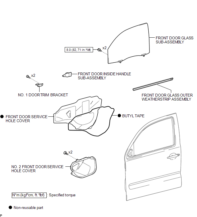
ILLUSTRATION

 Removal
REMOVAL
CAUTION / NOTICE / HINT
HINT:
Use the same procedure for the RH side and LH side.
The following procedure is for the LH side.
PROCEDURE
1. PRECAUTION
NOTICE:
After tur ...
Other materials:
Seat heaters
On
The indicator comes on.
Adjusts the seat temperature.
The further you turn the dial upward, the warmer the seat becomes.
■The seat heaters can be used when
The engine switch is in the ON position.
■When not in use
Turn the dial fully downward. The indicator turns off.
CAUT ...
Combination Meter ECU Communication Stop Mode
DESCRIPTION
Detection Item
Symptom
Trouble Area
Combination Meter ECU Communication Stop Mode
Either condition is met:
Communication stop for "Combination Meter" is indicated on the
"Communication Bus Ch ...
Rear Differential Lock Control SW Stuck ON (P17CC)
DESCRIPTION
This DTC is output when a malfunction of the differential lock switch is detected.
DTC No.
Detection Item
DTC Detection Condition
Trouble Area
P17CC
Rear Differential Lock Control SW Stuck ON
...
