Toyota Tacoma (2015-2018) Service Manual: Installation
INSTALLATION
CAUTION / NOTICE / HINT
HINT:
- Use the same procedure for the RH side and LH side.
- The following procedure is for the LH side.
PROCEDURE
1. INSTALL FRONT DOOR GLASS OUTER WEATHERSTRIP ASSEMBLY
|
(a) Engage the 5 claws to install the front door glass outer weatherstrip assembly. |
|
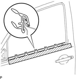
(b) Remove the protective tape.
2. INSTALL FRONT DOOR GLASS SUB-ASSEMBLY
Click here .gif)
3. INSTALL NO. 2 FRONT DOOR SERVICE HOLE COVER
Click here
4. INSTALL FRONT DOOR SERVICE HOLE COVER
Click here
5. INSTALL NO. 1 DOOR TRIM BRACKET
Click here
6. INSTALL FRONT DOOR INSIDE HANDLE SUB-ASSEMBLY
Click here
7. INSTALL OUTER REAR VIEW MIRROR ASSEMBLY
Click here
8. CONNECT CABLE TO NEGATIVE BATTERY TERMINAL
Torque:
5.4 N·m {55 kgf·cm, 48 in·lbf}
NOTICE:
When disconnecting the cable, some systems need to be initialized after the cable is reconnected.
Click here
9. INSPECT POWER WINDOW OPERATION
w/ Jam Protection Function:
Click here
w/o Jam Protection Function:
Click here
 Removal
REMOVAL
CAUTION / NOTICE / HINT
HINT:
Use the same procedure for the RH side and LH side.
The following procedure is for the LH side.
PROCEDURE
1. PRECAUTION
NOTICE:
After tur ...

Other materials:
Precaution
PRECAUTION
1. IGNITION SWITCH EXPRESSIONS
(a) The type of ignition switch used on this model differs according to the specifications
of the vehicle. The expressions listed in the table below are used in this section.
Expression
Ignition Switch (Position)
Engine ...
Installation
INSTALLATION
PROCEDURE
1. INSTALL REAR SEATBACK CENTER HINGE SUB-ASSEMBLY
(a) Install the rear seatback center hinge sub-assembly with the 2 bolts.
Torque:
30 N·m {306 kgf·cm, 22 ft·lbf}
2. INSTALL LUGGAGE COMPARTMENT SIDE TRAY
3. INSTALL REAR SEATBACK HINGE SUB-ASSEMBLY
(a) Install ...
Accessories, spare parts and modification of your Toyota
A wide variety of non-genuine spare parts and accessories for Toyota vehicles
are currently available in the market. You should know that Toyota does not warrant
these products and is not responsible for their performance, repair, or replacement,
or for any damage they may cause to, or adverse ...
