Toyota Tacoma (2015-2018) Service Manual: Automatic High Beam System does not Operate or Operation Indicator does not Illuminate
DESCRIPTION
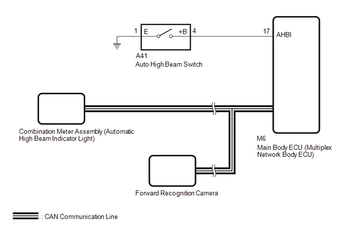
The main body ECU (multiplex network body ECU) controls the automatic high beam system based on signals received from the forward recognition camera.
WIRING DIAGRAM
CAUTION / NOTICE / HINT
NOTICE:
- When replacing the combination meter assembly, always replace it with a new one. If a combination meter assembly which was installed to another vehicle is used, the information stored in it will not match the information from the vehicle and a DTC may be stored.
- When replacing the forward recognition camera, always replace it with a new one. If a forward recognition camera which was installed to another vehicle is used, the information stored in the forward recognition camera will not match the information from the vehicle. As a result, a DTC may be stored.
- If the forward recognition camera has been replaced with a new one,
be sure to perform Forward Recognition Camera Learning.
Click here
.gif)
PROCEDURE
|
1. |
CHECK AUTOMATIC HIGH BEAM INDICATOR LIGHT |
(a) Check the operation of the automatic high beam indicator light.
- Turn the ignition switch to ON.
- Turn the light control switch to the Auto or Head position.
- Turn the headlight dimmer switch to the High position.
- Turn the automatic high beam main switch on.
OK:
Automatic high beam indicator light illuminates.
| NG | .gif) |
GO TO STEP 4 |
|
.gif)
|
2. |
READ VALUE USING TECHSTREAM |
(a) Using the Techstream, read the Data List.
Click here
|
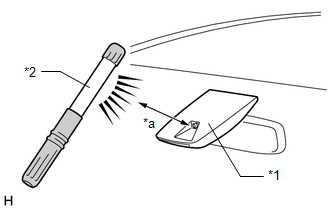
(1) Shine a light on the automatic high beam sensor*. HINT: *: If troubleshooting is being performed in a bright area, such as outside on a sunny day, it will not be necessary to perform this step. Main Body
OK: The Data List value displays "Daytime". |
|
| NG | |
REPLACE FORWARD RECOGNITION CAMERA |
|
|
3. |
READ VALUE USING TECHSTREAM |
(a) Using the Techstream, read the Data List.
Click here
|
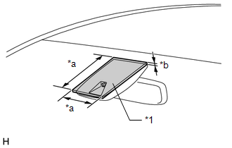
(1) Cover the automatic high beam sensor with an opaque object, such as cardboard. NOTICE:
OK: The Data List value displays "Speed". |
|
| OK | |
USE SIMULATION METHOD TO CHECK |
| NG | |
REPLACE FORWARD RECOGNITION CAMERA |
|
4. |
READ VALUE USING TECHSTREAM |
(a) Using the Techstream, read the Data List.
Click here
|
Tester Display |
Measurement Item / Range |
Normal Condition |
Diagnostic Note |
|---|---|---|---|
|
Auto High Beam Main Switch |
Auto high beam switch signal / OFF or ON |
OFF: Auto high beam switch off ON: Auto high beam switch on |
- |
OK:
Normal condition listed above is displayed.
| NG | |
GO TO STEP 7 |
|
|
5. |
READ VALUE USING TECHSTREAM |
(a) Using the Techstream, read the Data List.
Click here
|
Tester Display |
Measurement Item / Range |
Normal Condition |
Diagnostic Note |
|---|---|---|---|
|
Auto H Beam STS0 |
Automatic high beam sensor state past 0 / Undetec, CAM NA, No sens, Hlight, Taillgt, Speed, Daytime, Village, Malfunc, Delay, Aim Lmt, SAE Mod, Undefin, LIN Err |
Condition can be displayed |
- |
OK:
The Data List value displays "Daytime" or "Speed".
| NG | |
REPLACE FORWARD RECOGNITION CAMERA |
|
|
6. |
PERFORM ACTIVE TEST USING TECHSTREAM |
(a) Using the Techstream, perform the Active Test.
Click here
|
Tester Display |
Test Part |
Control Range |
Diagnostic Note |
|---|---|---|---|
|
Automatic High Beam Indicator |
Automatic high beam indicator light |
OFF or ON |
Operate with IG ON and the vehicle is stopped. |
OK:
Automatic high beam indicator light illuminates.
| OK | |
REPLACE MAIN BODY ECU (MULTIPLEX NETWORK BODY ECU) |
| NG | |
REPLACE COMBINATION METER ASSEMBLY |
|
7. |
INSPECT AUTO HIGH BEAM SWITCH |
(a) Remove the auto high beam switch.
Click here
(b) Inspect the auto high beam switch.
Click here
| NG | |
REPLACE AUTO HIGH BEAM SWITCH |
|
|
8. |
CHECK HARNESS AND CONNECTOR (AUTO HIGH BEAM SWITCH - MAIN BODY ECU [MULTIPLEX NETWORK BODY ECU] AND BODY GROUND) |
(a) Disconnect the A41 auto high beam switch connector.
(b) Disconnect the M6 main body ECU (multiplex network body ECU) connector.
(c) Measure the resistance according to the value(s) in the table below.
Standard Resistance:
|
Tester Connection |
Condition |
Specified Condition |
|---|---|---|
|
A41-4 (+B) - M6-17 (AHBI) |
Always |
Below 1 Ω |
|
A41-1 (E) - Body ground |
Always |
Below 1 Ω |
|
A41-4 (+B) or M6-17 (AHBI) - Body ground |
Always |
10 kΩ or higher |
| OK | |
REPLACE MAIN BODY ECU (MULTIPLEX NETWORK BODY ECU) |
| NG | |
REPAIR OR REPLACE HARNESS OR CONNECTOR |
 Lost Communication with Front Camera Module (U023A)
DESCRIPTION
These DTCs are stored when the CAN communication system is malfunctioning.
DTC No.
DTC Detecting Condition
Trouble Area
U023A
...
 IG Signal Circuit
DESCRIPTION
This circuit detects whether the ignition switch is ON or off, and sends this
information to the main body ECU (multiplex network body ECU).
WIRING DIAGRAM
CAUTION / NOTICE / HINT
...
Other materials:
Engine does not Start
DESCRIPTION
When the key is in the vehicle and the engine switch is pressed, the certification
ECU (smart key ECU assembly) receives a signal and changes the power source mode.
In addition, when the shift lever is in P or N and the brake pedal is depressed,
the engine can be started by pressi ...
Pressure Sensor or Switch (C1254)
DESCRIPTION
The accumulator pressure sensor is connected to the skid control ECU in the master
cylinder solenoid.
DTC No.
DTC Detecting Condition
Trouble Areas
C1254
Accumulator pressure sensor fault
(Fluid pressure does not chang ...
Master Cylinder Pressure Sensor Output Malfunction (Test Mode DTC) (C1281,...,C1458)
DESCRIPTION
DTC Code
DTC Detection Condition
Trouble Area
C1281
Stored only during test mode.
Master cylinder pressure sensor circuit
Skid control ECU, master cylinder pressure sensor (master cylinder
s ...
