Toyota Tacoma (2015-2018) Service Manual: Disassembly
DISASSEMBLY
PROCEDURE
1. FIX VANE PUMP
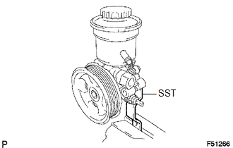
(a) Using SST, fix the vane pump assembly in a vise.
SST: 09630-00014
09631-00132
NOTICE:
When using a vise, do not overtighten it.
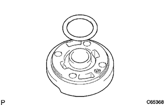
2. REMOVE VANE PUMP OIL RESERVOIR SUB-ASSEMBLY
(a) Remove the 3 bolts and vane pump oil reservoir.
(b) Remove the O-ring from the vane pump oil reservoir.
3. REMOVE FLOW CONTROL VALVE
(a) Remove the pressure port union.
(b) Remove the O-ring from the pressure port union.
(c) Remove the flow control valve and compression spring.
4. REMOVE POWER STEERING OIL PRESSURE SWITCH
NOTICE:
Be careful not to drop or badly damage the oil pressure switch. If damaged, replace it with a new one.
5. REMOVE VANE PUMP HOUSING REAR
(a) Remove the 4 bolts and vane pump housing rear from the vane pump housing front.
(b) Remove the O-ring from the vane pump housing front.
6. REMOVE PULLEY SHAFT SUB-ASSEMBLY
NOTICE:
Be careful not to drop or badly damage the pulley shaft. If damaged, replace it with a new one.
(a) Using a screwdriver, remove the snap ring from the pulley shaft.
(b) Remove the pulley shaft.
7. REMOVE VANE PUMP ROTOR
(a) Remove the 10 vane plates.
(b) Remove the vane pump rotor.
8. REMOVE VANE PUMP CAM RING
9. REMOVE VANE PUMP SIDE PLATE FRONT
(a) Remove the side plate from the vane pump housing front.
(b) Remove the O-ring from the side plate.
|
(c) Remove the O-ring from the vane pump housing front. |
|
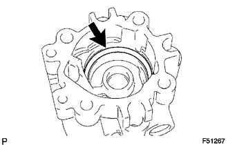
10. REMOVE VANE PUMP HOUSING OIL SEAL
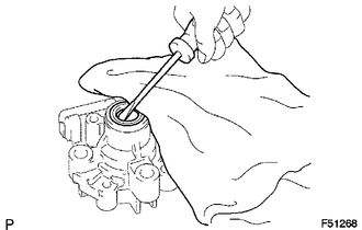
(a) Using screwdriver, remove the oil seal.
NOTICE:
Be careful not to damage the vane pump housing front.
 Components
COMPONENTS
ILLUSTRATION
ILLUSTRATION
...
 Removal
REMOVAL
PROCEDURE
1. PRECAUTION
NOTICE:
After turning the ignition switch off, waiting time may be required before disconnecting
the cable from the negative (-) battery terminal.
Therefore, mak ...
Other materials:
Inspection
INSPECTION
PROCEDURE
1. INSPECT SHIFT SOLENOID VALVE SL1
(a) Measure the resistance according to the value(s) in the table below.
Text in Illustration
*a
Component without harness connected
(Shift Solenoid Valve SL1)
Standa ...
Data List / Active Test
DATA LIST / ACTIVE TEST
1. READ DATA LIST
HINT:
Using the Techstream to read the Data List allows the values or states of switches,
sensors, actuators and other items to be read without removing any parts. This non-intrusive
inspection can be very useful because intermittent conditions or sig ...
Reassembly
REASSEMBLY
PROCEDURE
1. INSTALL STARTER ARMATURE ASSEMBLY
(a) Install the starter armature to the starter yoke.
2. INSTALL STARTER BRUSH HOLDER ASSEMBLY
(a) Install the starter brush holder assembly.
(b) Connect the 4 brushes to the starter brush holder assembly.
(1) Using a scre ...
