Toyota Tacoma (2015-2018) Service Manual: Removal
REMOVAL
PROCEDURE
1. REMOVE PROPELLER SHAFT WITH CENTER BEARING ASSEMBLY
|
(a) Place matchmarks on the propeller shaft flange and differential flange. Text in Illustration
|
|
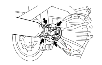
(b) for Differential Type BD20:
(1) Remove the 4 nuts, 4 bolts and 4 washers to disconnect the propeller shaft.
(c) for Differential Type BD22:
(1) Remove the 4 nuts and 4 washers to disconnect the propeller shaft.
|
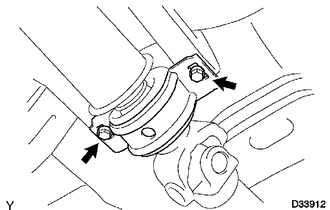
(d) Remove the 2 bolts to separate the center No. 2 support bearing assembly from the frame crossmember. |
|
|
(e) Pull out the propeller shaft. |
|
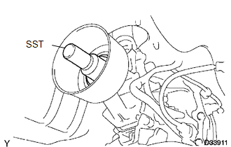
(f) Insert SST to the extension housing to prevent oil leakage.
SST: 09325-40010
 Components
COMPONENTS
ILLUSTRATION
...
 Disassembly
DISASSEMBLY
PROCEDURE
1. INSPECT PROPELLER SHAFT UNIVERSAL JOINT SPIDER BEARING
(a) Check the spider bearings for wear and damage.
(b) Check each spider bearings axial play by turning the yoke whi ...
Other materials:
Main Body ECU Vehicle Information Reading/Writing Process Malfunction (B15F6)
DESCRIPTION
This DTC is stored when items controlled by the main body ECU cannot be customized
via the navigation system vehicle customization screen.
HINT:
The main body ECU controls the items for the following systems that are customizable
via the navigation receiver assembly screen:
...
Transmission Range Sensor Circuit Malfunction (PRNDL Input) (P0705)
DESCRIPTION
The park/neutral position switch detects the shift lever position and sends signals
to the ECM.
DTC No.
DTC Detection Condition
Trouble Area
P0705
One of the following conditions is met:
(A) Any 2 or more of the followin ...
Inspection
INSPECTION
PROCEDURE
1. INSPECT BRAKE VACUUM CHECK VALVE ASSEMBLY
(a) Check that there is ventilation from the booster to the engine, and
no ventilation from the engine to the booster.
If the results are not as specified, replace the vacuum check valve.
...
