Toyota Tacoma (2015-2018) Service Manual: Components
COMPONENTS
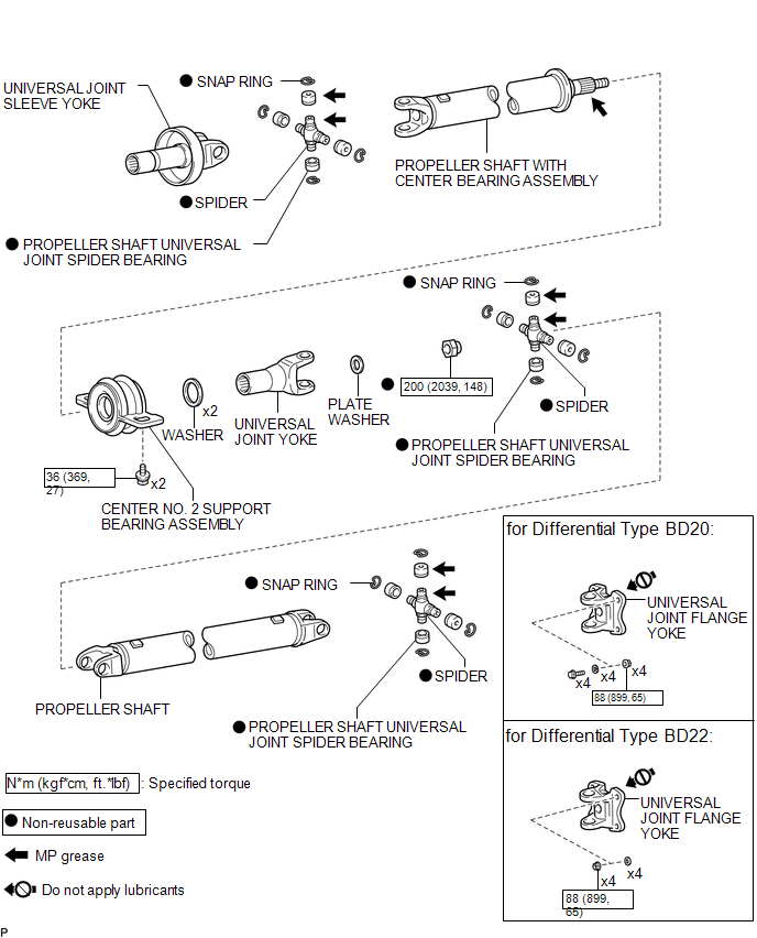
ILLUSTRATION

 Removal
REMOVAL
PROCEDURE
1. REMOVE PROPELLER SHAFT WITH CENTER BEARING ASSEMBLY
(a) Place matchmarks on the propeller shaft flange and differential flange.
Text in Illustration
...
Other materials:
Removal
REMOVAL
PROCEDURE
1. REMOVE PROPELLER SHAFT WITH CENTER BEARING ASSEMBLY
(a) Place matchmarks on the propeller shaft flange yoke and differential
flange.
Text in Illustration
*a
Matchmark
...
Precaution
PRECAUTION
1. PRECAUTIONS WHEN USING TECHSTREAM
(a) When using the Techstream to troubleshoot the engine immobiliser system:
Connect the Techstream to the DLC3 while the ignition switch is off, and turn
a door courtesy light switch on and off at 1.5-second intervals until communication
betwee ...
Installation
INSTALLATION
PROCEDURE
1. TEMPORARILY TIGHTEN FRONT SUSPENSION LOWER ARM
(a) Align the matchmarks on the camber adjust cam No. 2 and toe adjust cam. Temporarily
tighten the bolt and the nut.
(b) Install the front lower ball joint attachment, a new nut and a new cotter
pin.
Torque:
140 N ...
