Toyota Tacoma (2015-2018) Service Manual: Navigation Antenna
Components
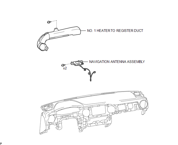
COMPONENTS
ILLUSTRATION
Installation
INSTALLATION
PROCEDURE
1. INSTALL NAVIGATION ANTENNA ASSEMBLY
(a) Install the navigation antenna assembly with the 2 screws.
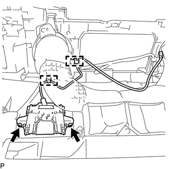
(b) Engage the 2 clamps.
2. INSTALL NO. 1 HEATER TO REGISTER DUCT
(See page .gif) )
)
3. INSTALL INSTRUMENT PANEL SUB-ASSEMBLY
(See page )
Removal
REMOVAL
PROCEDURE
1. REMOVE INSTRUMENT PANEL SUB-ASSEMBLY
(See page .gif) )
)
2. REMOVE NO. 1 HEATER TO REGISTER DUCT
(See page )
3. REMOVE NAVIGATION ANTENNA ASSEMBLY
|
(a) Disengage the 2 clamps. |
|
(b) Remove the 2 screws and navigation antenna assembly.

 Navigation Receiver
Components
COMPONENTS
ILLUSTRATION
ILLUSTRATION
Removal
REMOVAL
PROCEDURE
1. REMOVE INSTRUMENT CLUSTER CENTER FINISH PANEL SUB-ASSEMBLY
(See page )
2. REMOVE NAVIGATION RECEIVER ASS ...
Other materials:
Fail-safe Chart
FAIL-SAFE CHART
1. PULSE FAILURE OR DISPLACEMENT OF NON-DETECTION RANGE TO THE OPENING DIRECTION
(a) If the pulse sensor built into the power window regulator motor malfunctions,
the power window control system enters fail-safe mode.
Power Window Regulator Master Switch Assembly, Front Power Wi ...
Dtc Check / Clear
DTC CHECK / CLEAR
1. CHECK DTC
(a) Connect the Techstream to the DLC3.
(b) Turn the ignition switch to ON.
(c) Turn the Techstream on.
(d) Enter the following menus: Body Electrical / Smart Access or Main Body /
Trouble Codes.
(e) Check the details of the DTC(s) (See page
).
2. CLEAR DTC ...
On-vehicle Inspection
ON-VEHICLE INSPECTION
PROCEDURE
1. INSPECT OCCUPANT DETECTION ECU (for Vehicle not Involved in Collision)
(a) Perform a diagnostic system check (See page
).
2. INSPECT OCCUPANT DETECTION ECU (for Vehicle Involved in Collision)
(a) Perform a diagnostic system check (See page
).
(b) Even if ...
