Toyota Tacoma (2015-2018) Service Manual: Removal
REMOVAL
PROCEDURE
1. REMOVE NO. 1 ENGINE UNDER COVER SUB-ASSEMBLY
2. REMOVE FRONT EXHAUST PIPE ASSEMBLY
(See page .gif) )
)
3. REMOVE NO. 1 OIL COOLER INLET TUBE AND NO. 1 OIL COOLER OUTLET TUBE
NOTICE:
When disconnecting the hoses from the tube, support the tube by hand and be careful to prevent the tube from being deformed.
HINT:
Use a container to catch any ATF.
|
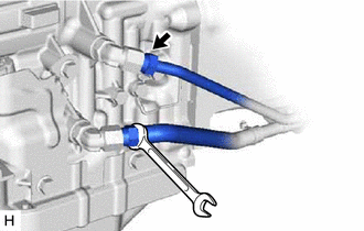
(a) Disconnect the No. 1 oil cooler inlet tube and No. 1 oil cooler outlet tube from the automatic transmission assembly. |
|
|
(b) Slide the 2 clips and disconnect the No. 1 oil cooler inlet hose and No. 1 oil cooler outlet hose from the No. 1 oil cooler inlet tube and No. 1 oil cooler outlet tube. |
|
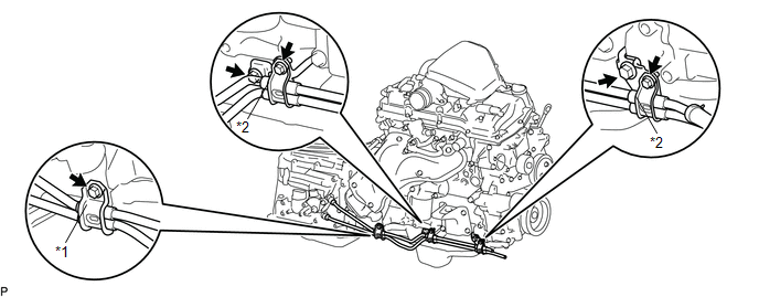
(c) Remove the bolt and flexible hose clamp from the automatic transmission assembly.
 Text in Illustration
|
*1 |
Flexible Hose Clamp |
*2 |
Oil Cooler Tube Clamp |
(d) Remove the 2 bolts to open the 2 oil cooler tube clamps and remove the No. 1 oil cooler inlet tube and No. 1 oil cooler outlet tube.
(e) Remove the 2 bolts and 2 oil cooler tube clamps from the engine assembly.
4. REMOVE NO. 1 OIL COOLER INLET HOSE AND NO. 1 OIL COOLER OUTLET HOSE
NOTICE:
When disconnecting the hoses from the tube, support the tube by hand and be careful to prevent the tube from being deformed.
HINT:
Use a container to catch any ATF.
|
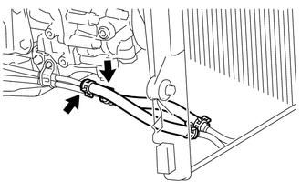
(a) Slide the 2 clips and remove the No. 1 oil cooler inlet hose and No. 1 oil cooler outlet hose from the oil cooler tube. |
|
5. REMOVE NO. 4 OIL COOLER INLET HOSE AND NO. 4 OIL COOLER OUTLET HOSE
NOTICE:
When disconnecting the hoses from the tube, support the tube by hand and be careful to prevent the tube from being deformed.
HINT:
Use a container to catch any ATF.
|
(a) Detach the claw to open the clamp. |
|
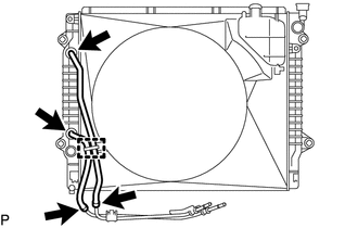
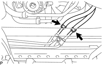
(b) Slide the 2 clips and disconnect the No. 4 oil cooler inlet hose and No. 4 oil cooler outlet hose from the oil cooler tube.
(c) Slide the 2 clips and remove the No. 4 oil cooler inlet hose and No. 4 oil cooler outlet hose from the radiator assembly.
6. REMOVE OIL COOLER TUBE
|
(a) Remove the 2 bolts and oil cooler tube from the vehicle body. |
|
.png)
 Installation
INSTALLATION
PROCEDURE
1. INSTALL OIL COOLER TUBE
(a) Install the oil cooler tube to the vehicle body with the 2 bolts.
Torque:
28 N·m {286 kgf·cm, 21 ft·lbf}
2. INSTALL NO. 4 OIL COOLER INL ...
 Oil Pump
...
Other materials:
Removal
REMOVAL
PROCEDURE
1. REMOVE AIR CONDITIONING CONTROL ASSEMBLY (for Automatic Air Conditioning System)
Click here
2. REMOVE AIR CONDITIONING CONTROL ASSEMBLY (for Manual Air Conditioning System)
Click here
3. REMOVE LOWER NO. 2 INSTRUMENT PANEL AIRBAG ASSEMBLY
Click here
4. REMOVE INSTR ...
Reassembly
REASSEMBLY
PROCEDURE
1. INSTALL NO. 2 ANTENNA CORD SUB-ASSEMBLY
(a) Using hot-melt glue, install the No. 2 antenna cord sub-assembly as shown
in the illustration.
2. INSTALL NO. 1 ROOF WIRE (w/ Vanity Light)
(a) w/ EC Mirror:
(1) Align the aiming tape as shown in the illustration.
...
Sending Malfunction (Navigation to APGS) (U0073,U0100,U0129,U0140,U0155,U0164)
DESCRIPTION
These DTCs are stored when a malfunction occurs in the CAN communication circuit.
DTC Code
DTC Detection Condition
Trouble Area
U0073
CAN bus connection error
CAN communication system
U0100
...
