Toyota Tacoma (2015-2018) Service Manual: Installation
INSTALLATION
PROCEDURE
1. INSTALL OIL COOLER TUBE
(a) Install the oil cooler tube to the vehicle body with the 2 bolts.
Torque:
28 N·m {286 kgf·cm, 21 ft·lbf}
2. INSTALL NO. 4 OIL COOLER INLET HOSE AND NO. 4 OIL COOLER OUTLET HOSE
NOTICE:
- When connecting the hoses to the tube, support the tube by hand and be careful to prevent the tube from being deformed.
- Make sure to install the clips so that the spool fitting is not overlapped.
(a) Install the No. 4 oil cooler inlet hose and No. 4 oil cooler outlet hose to the radiator assembly, and slide the 2 clips to secure them.
NOTICE:
Make sure to install any hose clips without a specific installation direction in a direction that does not interfere with other parts.
(b) Connect the No. 4 oil cooler inlet hose and No. 4 oil cooler outlet hose to the oil cooler tube, and slide the 2 clips to secure them.
NOTICE:
Make sure to install any hose clips without a specific installation direction in a direction that does not interfere with other parts.
(c) Then pass the No. 4 oil cooler inlet hose and No. 4 oil cooler outlet hose through the clamp and close the clamp.
3. INSTALL NO. 1 OIL COOLER INLET HOSE AND NO. 1 OIL COOLER OUTLET HOSE
NOTICE:
- When connecting the hoses to the tube, support the tube by hand and be careful to prevent the tube from being deformed.
- Make sure to install the clips so that the spool fitting is not overlapped.
(a) Install the No. 1 oil cooler inlet hose and No. 1 oil cooler outlet hose to the oil cooler tube, and slide the 2 clips to secure them.
NOTICE:
Make sure to install any hose clips without a specific installation direction in a direction that does not interfere with other parts.
4. INSTALL NO. 1 OIL COOLER INLET TUBE AND NO. 1 OIL COOLER OUTLET TUBE
NOTICE:
- When connecting the hoses to the tube, support the tube by hand and be careful to prevent the tube from being deformed.
- Make sure to install the clips so that the spool fitting is not overlapped.
(a) Install the 2 oil cooler tube clamps to the engine assembly with the 2 bolts.
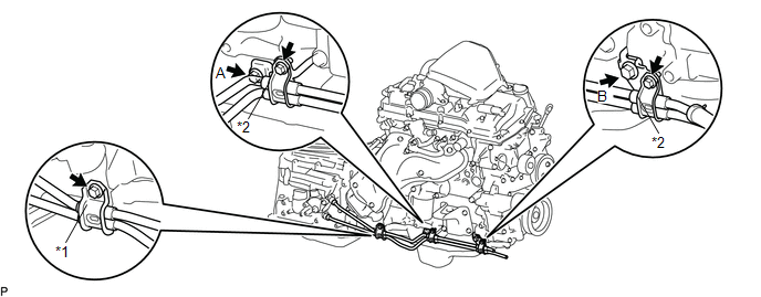 Text in Illustration
|
*1 |
Flexible Hose Clamp |
*2 |
Oil Cooler Tube Clamp |
Torque:
for Bolt A :
14 N·m {143 kgf·cm, 10 ft·lbf}
for Bolt B :
28 N·m {286 kgf·cm, 21 ft·lbf}
(b) Connect the ends of the No. 1 oil cooler inlet tube and No. 1 oil cooler outlet tube to the automatic transmission assembly by hand.
(c) Close the 2 oil cooler tube clamps and install the 2 bolts.
Torque:
5.5 N·m {56 kgf·cm, 49 in·lbf}
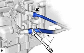
(d) Install the flexible hose clamp to the automatic transmission assembly with the bolt.
Torque:
14 N·m {143 kgf·cm, 10 ft·lbf}
(e) Connect the No. 1 oil cooler inlet hose and No. 1 oil cooler outlet hose to the No. 1 oil cooler inlet tube and No. 1 oil cooler outlet tube, and slide the 2 clips to secure them.
|
(f) Using a 17 mm union nut wrench, tighten the No. 1 oil cooler inlet tube and No. 1 oil cooler outlet tube. Text in Illustration
Torque: Specified tightening torque : 34 N·m {350 kgf·cm, 25 ft·lbf} HINT:
|
|
5. INSTALL FRONT EXHAUST PIPE ASSEMBLY
(See page .gif) )
)
6. ADD AUTOMATIC TRANSMISSION FLUID
(See page )
7. INSPECT FOR AUTOMATIC TRANSMISSION FLUID LEAK
8. INSTALL NO. 1 ENGINE UNDER COVER SUB-ASSEMBLY
Torque:
30 N·m {306 kgf·cm, 22 ft·lbf}
 Components
COMPONENTS
ILLUSTRATION
ILLUSTRATION
...
 Removal
REMOVAL
PROCEDURE
1. REMOVE NO. 1 ENGINE UNDER COVER SUB-ASSEMBLY
2. REMOVE FRONT EXHAUST PIPE ASSEMBLY
(See page )
3. REMOVE NO. 1 OIL COOLER INLET TUBE AND NO. 1 OIL COOLER OUTLET TUBE
NOTIC ...
Other materials:
Disassembly
DISASSEMBLY
PROCEDURE
1. REMOVE INTAKE VALVE
(a) Using SST, compress the inner compression spring and remove the valve
spring retainer locks.
SST: 09202-70020
SST: 09202-00021
09202-01010
09202-01020
(b) Remove the valve s ...
Transmitter ID not Received in Main Mode (C2126/26)
DESCRIPTION
After all transmitter IDs are registered, DTC C2126/26 is stored in the tire
pressure warning ECU and receiver and the tire pressure warning light blinks for
1 minute and then illuminates.
When the tire pressure warning ECU and receiver successfully receives radio waves
from all ...
Headlight Relay
Inspection
INSPECTION
PROCEDURE
1. INSPECT HEADLIGHT RELAY
(a) Check the resistance.
(1) Using an ohmmeter, measure the resistance between the terminals.
Standard:
Tester Connection
Specified Condition
3-5
10 kΩ or higher
...
