Toyota Tacoma (2015-2018) Service Manual: Driver Side Seat Belt Warning Light does not Operate
DESCRIPTION
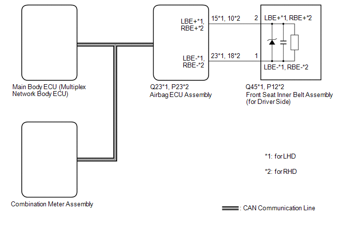
When the ignition switch is ON, the airbag sensor assembly transmits front seat inner belt status signals to the combination meter assembly through CAN. If the driver seat belt is not fastened, the combination meter assembly blinks the driver side seat belt warning light. If the seat belt is fastened, the warning light goes off.
NOTICE:
- Recognition code registration is necessary when replacing the main body ECU (multiplex network body ECU).
- If the main body ECU (multiplex network body ECU) is replaced, refer
to Registration (See page
.gif) ).*1
).*1
- *1: w/ Smart Key System
WIRING DIAGRAM
CAUTION / NOTICE / HINT
NOTICE:
The seat belt warning system uses the CAN communication system. First, confirm
that there are no malfunctions in the CAN communication system. Refer to How to
Proceed with Troubleshooting (See page ).
PROCEDURE
|
1. |
CHECK DTC OUTPUT (AIRBAG SYSTEM) |
(a) Clear the DTCs (See page ).
(b) Check for DTCs (See page ).
|
Result |
Proceed to |
|---|---|
|
DTCs are not output |
A |
|
DTCs are output |
B |
| B | .gif) |
GO TO AIRBAG SYSTEM |
|
.gif)
|
2. |
READ VALUE USING TECHSTREAM (LEFT SIDE BUCKLE SW) |
(a) Connect the Techstream to the DLC3.
(b) Turn the ignition switch to ON.
(c) Turn the Techstream on.
(d) Enter the following menus: Body Electrical / SRS Airbag / Data List.
(e) Read the Data List according to the display on the Techstream.
SRS Airbag|
Tester Display |
Measurement Item/Range |
Normal Condition |
Diagnostic Note |
|---|---|---|---|
|
Left side Buckle SW |
Driver side seat belt buckle switch/Unset, Set or NG |
Unset: Driver side seat belt unfastened Set: Driver side seat belt fastened NG: Data not determined |
- |
|
Result |
Proceed to |
|---|---|
|
Unset or Set is displayed on the Techstream according to the driver seat belt condition |
A |
|
Unset or Set is not displayed correctly on the Techstream according to the driver seat belt condition |
B |
|
NG is displayed on the Techstream |
C |
| B | |
REPLACE FRONT SEAT INNER BELT ASSEMBLY LH |
| C | |
REPLACE AIRBAG SENSOR ASSEMBLY |
|
|
3. |
REPLACE MAIN BODY ECU |
(a) Temporarily replace the main body ECU with a new or known good one (See page
).
|
|
4. |
CHECK SEAT BELT WARNING LIGHT |
(a) Check the operation of the seat belt warning light (See page
).
OK:
The seat belt warning light operates normally.
| OK | |
END (MAIN BODY ECU WAS DEFECTIVE) |
| NG | |
REPLACE COMBINATION METER ASSEMBLY |
 Terminals Of Ecu
TERMINALS OF ECU
1. CHECK COMBINATION METER ASSEMBLY
(a) Measure the resistance and voltage according to the value(s) in the table
below.
Terminal No. (Symbol)
Wiring Colo ...
 On-vehicle Inspection
ON-VEHICLE INSPECTION
PROCEDURE
1. INSPECT DRIVER SEAT BELT WARNING LIGHT
HINT:
The seat belt warning light on the combination meter assembly is used for both
the driver seat and front passenger ...
Other materials:
Detachable pole antenna
The antenna can be removed.
■ Removing the antenna
Place the included wrench around the antenna.
When not in use, the wrench is stored in glove box.
Loosen the antenna with the wrench and remove it.
■ Installing the antenna
Tighten the antenna by one hand until it will not t ...
Components
COMPONENTS
ILLUSTRATION
*A
for Double Cab
*B
w/o Woofer
*C
w/ Woofer
-
-
*1
LUGGAGE COMPARTMENT SIDE TRAY RH
-
-
ILLUSTRATION
*A ...
Center Differential Lock Position Switch (C1282)
DESCRIPTION
DTC C1282 is stored only in test mode.
DTC Code
DTC Detection Condition
Trouble Area
C1282
Stored during test mode.
Harness or connector
Transfer system
Skid control ECU (master cylinder sole ...
