Toyota Tacoma (2015-2018) Service Manual: Starter Relay
Inspection
INSPECTION
PROCEDURE
1. INSPECT STARTER RELAY
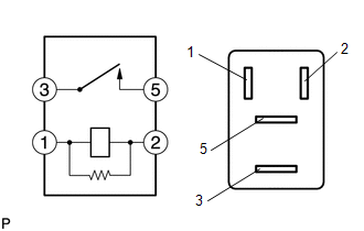
(a) Check the resistance.
(1) Measure the resistance according to the value(s) in the table below.
Standard Resistance:
|
Tester Connection |
Connection |
Specified Condition |
|---|---|---|
|
3 - 5 |
Battery voltage not applied to terminals 1 and 2 |
10 kΩ or higher |
|
3 - 5 |
Battery voltage applied to terminals 1 and 2 |
Below 1 Ω |
If the result is not as specified, replace the starter relay.
 Reassembly
REASSEMBLY
PROCEDURE
1. INSTALL STARTER ARMATURE ASSEMBLY
(a) Install the starter armature to the starter yoke.
2. INSTALL STARTER BRUSH HOLDER ASSEMBLY
(a) Install the starter brush holder assem ...
 Starting System
Parts Location
PARTS LOCATION
ILLUSTRATION
ILLUSTRATION
Precaution
PRECAUTION
1. IGNITION SWITCH EXPRESSIONS
(a) The type of ignition switch used on this model differs depending on the ...
Other materials:
Lost Communication with Brake System Control Module (U0129/29)
DESCRIPTION
The tire pressure warning ECU and receiver receives signals from the skid control
ECU (brake actuator assembly) via the CAN communication system.
DTC No.
DTC Detection Condition
Trouble Area
U0129/29
Lost communication with ...
Hazard Warning Switch Circuit
DESCRIPTION
The combination meter assembly receives information signals from the telltale
light assembly (hazard warning signal switch).
WIRING DIAGRAM
CAUTION / NOTICE / HINT
NOTICE:
Inspect the fuses for circuits related to this system before performing the following
inspection procedur ...
Terminals Of Ecm
TERMINALS OF ECM
HINT:
The standard normal voltage between each pair of ECM terminals is shown in the
table below. The appropriate conditions for checking each pair of terminals are
also indicated. The result of checks should be compared with the standard normal
voltage for that pair of te ...
