Toyota Tacoma (2015-2018) Service Manual: Pressure Control Solenoid "D" Electrical (Shift Solenoid Valve SLT) (P2716)
DESCRIPTION
Refer to the system description for DTC P2714 (See page
.gif) ).
).
|
DTC No. |
DTC Detection Condition |
Trouble Area |
|---|---|---|
|
P2716 |
Open or short is detected in shift solenoid valve SLT circuit for 1 second or more while driving (1 trip detection logic). |
|
MONITOR DESCRIPTION
When an open or short in the shift solenoid valve SLT circuit is detected, the ECM interprets this as a fault. The ECM will illuminate the MIL and store the DTC.
MONITOR STRATEGY
|
Related DTCs |
P2716: Shift solenoid valve SLT/Range check |
|
Required sensors/Components |
Shift solenoid valve SLT |
|
Frequency of operation |
Continuous |
|
Duration |
1 sec. |
|
MIL operation |
Immediately |
|
Sequence of operation |
None |
TYPICAL ENABLING CONDITIONS
All:|
The monitor will run whenever the following DTCs are not stored |
None |
|
Solenoid current cut status |
Not cut |
|
Ignition switch |
ON |
|
Starter |
OFF |
|
Battery voltage |
12 V or higher |
|
Battery voltage |
10 V or higher, and below 12 V |
|
Target current |
Below 0.75 A |
|
Battery voltage |
8 V or higher |
|
Target current |
0.25 A or higher |
|
Battery voltage |
11 V or higher |
|
Target current |
1 A or higher |
|
Battery voltage |
11 V or higher |
|
Target current |
0.1 A or more |
|
l Target voltage - Last Target voltage l |
Less than 0.000019 V |
TYPICAL MALFUNCTION THRESHOLDS
One of the following conditions is met: Condition (A), (B), (C) or (D)
Condition (A) and (B):|
Output duty cycle |
100% or more |
|
Output duty cycle |
0% or less |
|
Solenoid voltage monitor |
No signal |
|
l Target voltage - Average of monitor voltage l |
0.035 V or more |
COMPONENT OPERATING RANGE
|
Output duty cycle |
More than 3%, and less than 100% |
|
Solenoid voltage monitor |
Signal input |
|
l Target voltage - Average of monitor voltage l |
Less than 0.035 V |
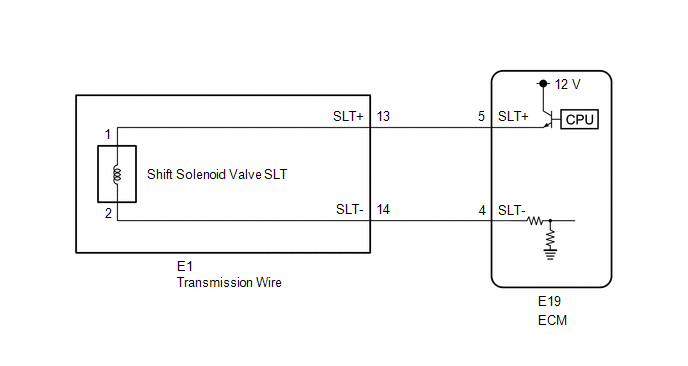
WIRING DIAGRAM
CAUTION / NOTICE / HINT
NOTICE:
- Perform the universal trip to clear permanent DTCs (See page
).
- Perform registration and/or initialization when parts related to the
automatic transmission are replaced (See page
).
HINT:
After the repair, clear the DTCs and perform the following procedure to check that DTCs are not output.
- Start the engine.
- Check for DTCs again (See page ).
PROCEDURE
|
1. |
INSPECT TRANSMISSION WIRE (SHIFT SOLENOID VALVE SLT) |
|
(a) Disconnect the E1 transmission wire connector. |
|
(b) Measure the resistance according to the value(s) in the table below.
Standard Resistance:
|
Tester Connection |
Condition |
Specified Condition |
|---|---|---|
|
13 (SLT+) - 14 (SLT-) |
20°C (68°F) |
5.0 to 5.6 Ω |
|
13 (SLT+) - Body ground |
Always |
10 kΩ or higher |
|
14 (SLT-) - Body ground |
Always |
10 kΩ or higher |
|
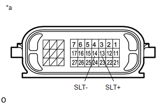
*a |
Component without harness connected (Transmission Wire) |
| NG | .gif) |
GO TO STEP 3 |
|
.gif)
|
2. |
CHECK HARNESS AND CONNECTOR (TRANSMISSION WIRE - ECM) |
|
(a) Disconnect the ECM connector. |
|
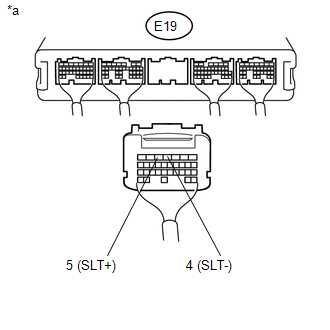
(b) Measure the resistance according to the value(s) in the table below.
Standard Resistance:
|
Tester Connection |
Condition |
Specified Condition |
|---|---|---|
|
E19-5 (SLT+) - E19-4 (SLT-) |
20°C (68°F) |
5.0 to 5.6 Ω |
|
E19-5 (SLT+) - Body ground |
Always |
10 kΩ or higher |
|
E19-4 (SLT-) - Body ground |
Always |
10 kΩ or higher |
|
*a |
Rear view of wire harness connector (to ECM) |
| OK | |
REPLACE ECM |
| NG | |
REPAIR OR REPLACE HARNESS OR CONNECTOR |
|
3. |
INSPECT SHIFT SOLENOID VALVE SLT |
|
(a) Remove shift solenoid valve SLT (See page
|
|
.png)
(b) Measure the resistance according to the value(s) in the table below.
Standard Resistance:
|
Tester Connection |
Condition |
Specified Condition |
|---|---|---|
|
1 - 2 |
20°C (68°F) |
5.0 to 5.6 Ω |
(c) Apply 12 V battery voltage to the shift solenoid valve and check that the valve moves and makes an operating noise.
OK:
|
Measurement Condition |
Specified Condition |
|---|---|
|
Valve moves and makes an operating noise |
|
*1 |
Shift Solenoid Valve SLT |
| OK | |
REPLACE TRANSMISSION WIRE |
| NG | |
REPLACE SHIFT SOLENOID VALVE SLT |
 Vehicle Control History
VEHICLE CONTROL HISTORY
VEHICLE CONTROL HISTORY
(a) A part of the control history can be confirmed using the vehicle control
history.
Click here ...
 Transmission Fluid Temperature Sensor "B" Circuit Low Input (P2742,P2743)
DESCRIPTION
The No. 2 ATF temperature sensor is installed in the transmission valve body
assembly.
If the ECM detects an abnormally high ATF temperature near this sensor, it illuminates
the warn ...
Other materials:
Reassembly
REASSEMBLY
PROCEDURE
1. INSTALL BRAKE BOOSTER ACCUMULATOR ASSEMBLY
(a) Place the brake booster pump in a vise with a cloth.
(b) Install the brake booster accumulator pipe, compression spring and a new
O-ring.
NOTICE:
Ensure that no foreign matter enters the pump.
(c) Using a socket wrench ...
Disassembly
DISASSEMBLY
PROCEDURE
1. REMOVE TELEPHONE MICROPHONE ASSEMBLY
Click here
2. REMOVE MICROPHONE CASE
HINT:
Use the same procedure for Double Cab.
Click here
3. REMOVE NO. 1 ROOF WIRE (w/ Vanity Light)
(a) w/ EC Mirror:
(1) Remove the No. 1 roof wire.
...
Customize Parameters
CUSTOMIZE PARAMETERS
1. CUSTOMIZE POWER DOOR LOCK CONTROL SYSTEM
HINT:
The following items can be customized.
NOTICE:
When the customer requests a change in a function, first make sure that
the function can be customized.
Be sure to make a note of the current settings before cus ...
