Toyota Tacoma (2015-2018) Service Manual: Installation
INSTALLATION
PROCEDURE
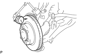
1. INSTALL FRONT DISC
|
(a) Align the matchmarks of the front disc and the front axle hub and install the front disc. Text in Illustration
HINT: When replacing the disc with a new one, select the installation position where the disc has the minimum runout. |
|
.png)
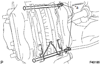
2. INSPECT DISC RUNOUT
(a) Temporarily install the front disc with the hub nuts.
Torque:
113 N·m {1152 kgf·cm, 83 ft·lbf}
|
(b) Using a dial indicator, measure the disc runout 10 mm (0.394 in.) away from the outer edge of the front disc. Maximum disc runout: 0.05 mm (0.00197 in.) If the disc runout is the maximum value or greater, check the bearing
play in the axial direction and check the axle hub runout (See page
|
|
3. INSTALL DISC BRAKE CYLINDER ASSEMBLY
(a) Install the disc brake cylinder assembly with the 2 bolts.
Torque:
123 N·m {1254 kgf·cm, 91 ft·lbf}
(b) Using a union nut wrench 10 mm, install the brake tube to the disc brake cylinder assembly.
Torque:
15 N·m {155 kgf·cm, 11 ft·lbf}
NOTICE:
Use the formula to calculate special torque values for situations where a union
nut wrench is combined with a torque wrench (See page
.gif) ).
).
4. INSTALL FRONT ANTI SQUEAL SHIM KIT
(a) Install the 2 front anti squeal shims onto each of the front disc brake pads.
NOTICE:
If necessary, replace the anti-squeal shim kit when replacing the brake pad.
5. INSTALL FRONT DISC BRAKE PAD KIT
(a) Install the 2 front disc brake pads with front anti-squeal shim onto the disc brake cylinder assembly.
NOTICE:
There should be no oil or grease on the friction surfaces of the brake pads and the front disc.
6. INSTALL FRONT DISC BRAKE ANTI-RATTLE WITH HOLE PIN
(a) for Pin Hold Clip Type A:
(1) Install the anti-rattle spring to the front disc brake pad.
NOTICE:
The anti-rattle spring can be used again if it has sufficient rebound; no deformation, cracks or wear; and has had all rust, dirt and foreign matter cleaned off.
(2) Install the 2 front disc brake anti-rattle with hole pins to the disc brake cylinder assembly.
(3) Install the pin hold clip to the 2 front disc brake anti-rattle with hole pins.
NOTICE:
The pin hold clip can be used again if it has sufficient rebound; no deformation or wear; and has had all rust, dirt and foreign matter cleaned off.
(b) for Pin Hold Clip Type B:
(1) Install the anti-rattle spring to the front disc brake pad.
NOTICE:
The anti-rattle spring can be used again if it has sufficient rebound; no deformation, cracks or wear; and has had all rust, dirt and foreign matter cleaned off.
(2) Install the 2 front disc brake anti-rattle with hole pins to the disc brake cylinder assembly.
|
(3) Install 2 new pin hold clips to the 2 front disc brake anti-rattle with hole pins. Text in Illustration
NOTICE: Be sure to install the pin hold clip with the handle facing to the vehicle center. |
|
7. FILL RESERVOIR WITH BRAKE FLUID (for Hydraulic Brake Booster)
8. FILL RESERVOIR WITH BRAKE FLUID (for Vacuum Brake Booster)
9. BLEED BRAKE BOOSTER WITH ACCUMULATOR PUMP ASSEMBLY (for Hydraulic Brake Booster)
10. BLEED MASTER CYLINDER (for Vacuum Brake Booster)
11. BLEED BRAKE LINE (for Hydraulic Brake Booster)
12. BLEED BRAKE LINE (for Vacuum Brake Booster)
13. BLEED MASTER CYLINDER SOLENOID (for Hydraulic Brake Booster)
14. BLEED BRAKE ACTUATOR (for Vacuum Brake Booster)
15. INSPECT FLUID LEVEL IN RESERVOIR (for Hydraulic Brake Booster)
16. INSPECT FLUID LEVEL IN RESERVOIR (for Vacuum Brake Booster)
17. INSPECT FOR BRAKE FLUID LEAK
18. INSTALL FRONT WHEEL
Torque:
113 N·m {1152 kgf·cm, 83 ft·lbf}
 Inspection
INSPECTION
PROCEDURE
1. INSPECT BRAKE CYLINDER AND PISTON
(a) Check the cylinder bore and piston for rust and scoring.
2. INSPECT PAD LINING THICKNESS
(a) Using a ruler, measure the pad lining ...
 Reassembly
REASSEMBLY
PROCEDURE
1. TEMPORARILY TIGHTEN FRONT DISC BRAKE BLEEDER PLUG
(a) Provisionally tighten the bleeder plug to the disc brake cylinder.
(b) Install the bleeder plug cap onto the bleeder p ...
Other materials:
Diagnostic Trouble Code Chart
DIAGNOSTIC TROUBLE CODE CHART
Intuitive Parking Assist System
DTC Code
Detection Item
See page
C1AE6
Rear Left Sensor Malfunction
C1AE7
Rear Left Center Sensor Malfunction
...
Disassembly
DISASSEMBLY
PROCEDURE
1. INSPECT PROPELLER SHAFT UNIVERSAL JOINT SPIDER BEARING
(a) Check the spider bearings for wear and damage.
(b) Check each spider bearings axial play by turning the yoke while holding the
shaft tightly.
Maximum bearing axial play:
0 to 0.05 mm (0 to 0.00197 in.)
If t ...
Components
COMPONENTS
ILLUSTRATION
ILLUSTRATION
ILLUSTRATION
ILLUSTRATION
...
