Toyota Tacoma (2015-2018) Service Manual: Reassembly
REASSEMBLY
CAUTION / NOTICE / HINT
CAUTION:
Wear protective gloves. Sharp areas on the parts may injure your hands.
PROCEDURE
1. INSTALL SEPARATE TYPE REAR SEATBACK COVER
|
(a) Using hog ring pliers, install the separate type rear seatback cover with 2 new hog rings. Text in Illustration
NOTICE:
|
|
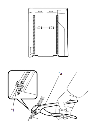
(b) Engage the 2 hook-and-loop fasteners.
2. INSTALL REAR SEAT LOCK HANDLE
|
(a) Install the rear seat lock handle into the rear seatback lock. |
|
.png)
3. INSTALL REAR SEATBACK LOCK ASSEMBLY
|
(a) Install the rear seatback lock assembly with the 2 bolts. Torque: 30 N·m {306 kgf·cm, 22 ft·lbf} |
|
.png)
4. INSTALL REAR SEATBACK FRAME SUB-ASSEMBLY
|
(a) Engage the 2 hooks to install the rear seatback frame sub-assembly. |
|
.png)
|
(b) Engage the 2 hooks. |
|
.png)
|
(c) Connect the 2 rear seatback cover straps. |
|
.png)
5. INSTALL REAR SEAT HEADREST SUPPORT
.png)
(a) Engage the 4 claws and install the 2 rear seat headrest supports.
6. INSTALL REAR SEATBACK BOARD SUB-ASSEMBLY
|
(a) Engage the 4 claws to install the rear seatback board sub-assembly. |
|
.png)
(b) Install the 2 screws.
7. INSTALL REAR SEAT HEADREST ASSEMBLY
(a) Disengage the 2 lock buttons of the 2 rear seat headrest supports to install the rear seat headrest assembly.
8. INSTALL SEPARATE TYPE REAR SEAT CUSHION COVER
|
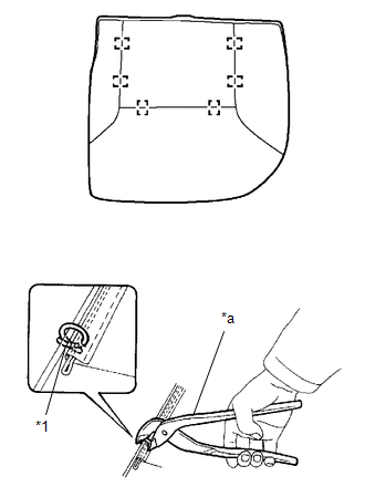
(a) Using hog ring pliers, install the separate type rear seat cushion cover with 6 new hog rings. Text in Illustration
NOTICE:
|
|
9. INSTALL REAR SEAT CUSHION FRAME SUB-ASSEMBLY
|
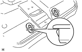
(a) Engage the hook to install the rear seat cushion frame sub-assembly. |
|
.png)
10. INSTALL REAR SEAT CUSHION HINGE SUB-ASSEMBLY
|
(a) Install the 2 rear seat cushion hinge sub-assemblies with the 2 bolts. Torque: 21 N·m {214 kgf·cm, 15 ft·lbf} |
|
.png)
11. INSTALL REAR SEAT HEADREST HOLDER
|
(a) Engage the 4 claws to install the 2 rear seat headrest holders. |
|
12. INSTALL REAR SEAT CUSHION BAND
|
(a) Install the rear seat cushion band with the screw. |
|
.png)
 Installation
INSTALLATION
PROCEDURE
1. INSTALL REAR SEATBACK CENTER HINGE SUB-ASSEMBLY
(a) Install the rear seatback center hinge sub-assembly with the 2 bolts.
Torque:
30 N·m {306 kgf·cm, 22 ft·lbf}
2. ...

Other materials:
System Diagram
SYSTEM DIAGRAM
Communication Table
Sender
Receiver
Signal
Line
ECM
Combination Meter Assembly
Cruise main indicator light signal
CAN
Skid Control ECU
ECM
Vehicle st ...
Installation
INSTALLATION
PROCEDURE
1. INSTALL CAMSHAFT TIMING OIL CONTROL SOLENOID ASSEMBLY (for Intake Side of
Bank 1)
(a) Apply engine oil to a new O-ring and install it to the camshaft timing
oil control solenoid assembly in the locations shown in the illustration.
Text in Illustration ...
Components
COMPONENTS
ILLUSTRATION
ILLUSTRATION
ILLUSTRATION
ILLUSTRATION
...
