Toyota Tacoma (2015-2018) Service Manual: Reassembly
REASSEMBLY
PROCEDURE
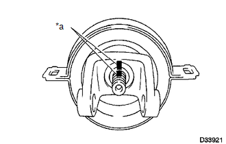
1. INSPECT CENTER NO. 2 SUPPORT BEARING ASSEMBLY
.png)
(a) Turn the center bearing by hand, check that it turns smoothly without catching and that there are no cracks or damage.
If there are any defects, replace it.
2. INSTALL CENTER NO. 2 SUPPORT BEARING ASSEMBLY
(a) Install the center support bearing onto the propeller shaft with center bearing assembly.
.png) Text in Illustration
Text in Illustration
.png) |
Front |
(b) Coat the splines of the intermediate shaft with MP grease.
(c) Install the 2 washers.
|
(d) Align the matchmarks on the center yoke and propeller shaft with center bearing assembly. Text in Illustration
HINT: If replacing either the center yoke or propeller shaft with center bearing assembly, reassemble them so that the front side yoke of the intermediate shaft and the center yoke are facing in the same direction. |
|
(e) Install the spacer.
(f) Fix the yoke at the center bearing section in a vice.
(g) Clamp the yoke in a vise, and press the bearing into position by tightening a new nut.
Torque:
200 N·m {2039 kgf·cm, 148 ft·lbf}
(h) Using a chisel and hammer, stake the lock nut.
3. INSTALL PROPELLER SHAFT UNIVERSAL JOINT SPIDER BEARING
.png)
(a) Apply MP grease to a new spider and bearings.
(b) Fit the spider into the flange yoke.
|
(c) Measure dimension A between the snap ring grooves. |
|
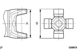
(d) Insert the spider bearing into the spider journal portion, and then measure dimension B of the universal joint.
NOTICE:
When measuring dimension B, fix the spider and needle roller bearings in a vise and hold them firmly together.
|
(e) Select snap rings to make dimensions A and B the same. Snap Ring Type:
NOTICE:
|
|
.png)
|
(f) Insert the spider into the yoke, and then using SST, press the spider bearing into the snap ring groove. Text in Illustration
SST: 09332-25010 |
|
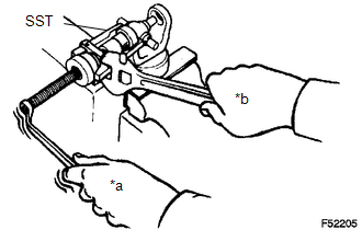
(g) Press in the spider bearing on the opposite side in the same way.
NOTICE:
When pressing in the spider bearing, be careful not to damage its lip.
|
(h) Using needle-nose pliers, install new snap rings into the grooves of the yoke. |
|
.png)
4. INSPECT PROPELLER SHAFT UNIVERSAL JOINT SPIDER BEARING
(a) Check the spider bearings for wear and damage.
(b) Check each spider bearing's axial play by turning the yoke while holding the shaft tightly.
Maximum bearing axial play:
0 to 0.05 mm (0 to 0.00196 in.)
5. INSTALL REAR PROPELLER SHAFT BOOT CLAMP
(a) Temporarily install a new rear sliding shaft boot to the propeller shaft with 2 new rear propeller shaft boot clamps.
(b) Coat the splines of the propeller shaft with grease.
Standard grease capacity:
7.0 to 10.0 g (0.2 to 0.4 oz.)
(c) Align the matchmarks on the propeller shaft and sleeve yoke.
(d) Install the sleeve yoke to the propeller shaft and connect the rear sliding shaft boot.
(e) Align the matchmarks on the propeller shaft, sleeve yoke and the pinching portions of the 2 rear propeller shaft boot clamps.
HINT:
Make sure to align the matchmarks of the propeller shaft boot clamp.
If the pinching portions are installed at different locations than where they were located before disassembly, the rotational balance of the propeller shaft cannot be ensured, which may result in vibrations and noise.
(f) Secure one of the rear propeller shaft boot clamps to the rear sliding shaft boot.
HINT:
- Use the same procedure for each rear propeller shaft boot clamp.
- Make sure that the matchmarks of the pinching portion of the rear propeller shaft boot clamp are aligned.
|
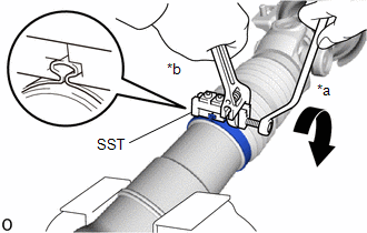
*a |
Turn |
|
*b |
Hold |
(1) Install SST to the rear propeller shaft boot clamp, and then while pressing the rear sliding shaft boot, slightly tighten the SST bolt.
SST: 09521-24010
NOTICE:
- Correctly set the rear propeller shaft boot clamp to the guide groove.
- Do not damage the rear sliding shaft boot.
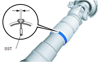
(2) Tighten SST so that the rear propeller shaft boot clamp is pinched.
Standard clearance:
3.8 mm (0.150 in.) or less
NOTICE:
- When tightening SST, make sure the clearance of the rear propeller shaft boot clamp is within the standard clearance.
- Do not damage the rear sliding shaft boot.
(3) Remove SST from the rear propeller shaft boot clamp.
|
(4) Using SST, measure the clearance of the rear propeller shaft boot clamp. SST: 09240-00020 Standard clearance: 3.8 mm (0.150 in.) or less NOTICE: If the measured value exceeds the specified value, retighten the rear propeller shaft boot clamp. |
|
 Installation
INSTALLATION
PROCEDURE
1. INSPECT PROPELLER SHAFT WITH CENTER BEARING ASSEMBLY (with Grease Fitting)
Text in Illustration
*1
Grease Fitting
-
-
...
 Propeller Shaft System
Problem Symptoms Table
PROBLEM SYMPTOMS TABLE
HINT:
Use the table below to help determine the cause of problem symptoms. If multiple
suspected areas are listed, the potential causes of the symp ...
Other materials:
Screen Flicker or Color Distortion
PROCEDURE
1.
CHECK DISPLAY SETTING
(a) Reset display settings (contrast, brightness) and check that the screen appears
normal.
OK:
The display returns to normal.
OK
END
NG
PROCEED TO NEXT SUSPECTED AREA SHOWN IN ...
Installation
INSTALLATION
PROCEDURE
1. INSTALL FORWARD RECOGNITION CAMERA
NOTICE:
When replacing the forward recognition camera, replace it with a new
one.
Do not touch the camera lens. If the camera lens has been touched, do
not use the forward recognition camera.
If the forward reco ...
Installation
INSTALLATION
PROCEDURE
1. INSTALL CHARCOAL CANISTER LEAK DETECTION PUMP SUB-ASSEMBLY
(a) Engage the 2 claws to install a new charcoal canister leak detection
pump sub-assembly to the charcoal canister assembly.
NOTICE:
Do not allow foreign matter such as grease, ...
