Toyota Tacoma (2015-2018) Service Manual: Installation
INSTALLATION
PROCEDURE
1. INSPECT PROPELLER SHAFT WITH CENTER BEARING ASSEMBLY (with Grease Fitting)
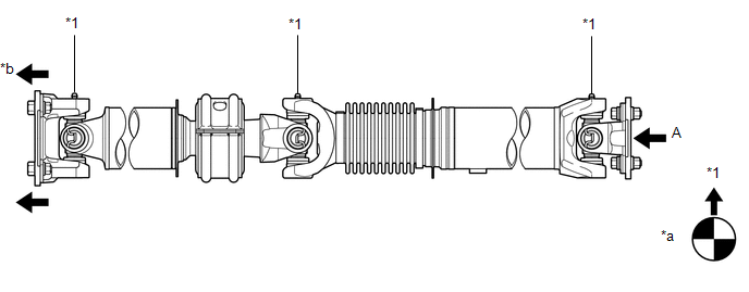 Text in Illustration
|
*1 |
Grease Fitting |
- |
- |
|
*a |
View A |
*b |
Front Side |
HINT:
When replacing the spider bearing, make sure that the grease fitting assembly hole is facing in the direction shown in the illustration.
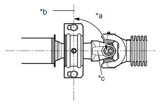
2. INSTALL PROPELLER SHAFT WITH CENTER BEARING ASSEMBLY
|
(a) Align the matchmarks on the propeller shaft flange yoke and transfer flange. Text in Illustration
|
|
(b) Install the propeller shaft with the 4 nuts and 4 washers.
Torque:
88 N·m {899 kgf·cm, 65 ft·lbf}
|
(c) Align the matchmarks on the propeller shaft flange yoke and differential flange. Text in Illustration
|
|
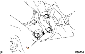
(d) for Differential Type BD20:
(1) Install the propeller shaft with the 4 bolts, 4 washers and 4 nuts.
Torque:
88 N·m {899 kgf·cm, 65 ft·lbf}
(e) for Differential Type BD22:
(1) Install the propeller shaft with the 4 washers and 4 nuts.
Torque:
88 N·m {899 kgf·cm, 65 ft·lbf}
|
(f) Provisionally install the center support bearing with 2 mounting bolts. Text in Illustration
HINT: Make sure the bearing is installed with the drain hole facing downwards. |
|
(g) Tighten the 2 bolts.
Torque:
36 N·m {369 kgf·cm, 27 ft·lbf}
 Inspection
INSPECTION
PROCEDURE
1. INSPECT PROPELLER SHAFT WITH CENTER BEARING ASSEMBLY
(a) Using a dial indicator, check the propeller shaft runout.
Maximum runout:
0.6 mm (0.0236 in.)
If the shaft run ...
 Reassembly
REASSEMBLY
PROCEDURE
1. INSPECT CENTER NO. 2 SUPPORT BEARING ASSEMBLY
(a) Turn the center bearing by hand, check that it turns smoothly without catching
and that there are no cracks or damage.
...
Other materials:
Installation
INSTALLATION
PROCEDURE
1. INSTALL COOLER CONDENSER ASSEMBLY
(a) Engage the 2 claws to install the 2 condenser upper brackets.
(b) Engage the 2 claws to install the 2 condenser lower brackets.
(c) Lift the cooler condenser assembly up from the rear side of the vehicle,
and install ...
ECU Malfunction (B1003)
DESCRIPTION
DTC No.
DTC Detection Condition
Trouble Area
B1003
A malfunction in the non-volatile storage of the central gateway ECU
(network gateway ECU) is detected.
Central gateway ECU (network gateway ECU)
PROC ...
License Plate Light Assembly
Components
COMPONENTS
ILLUSTRATION
Removal
REMOVAL
CAUTION / NOTICE / HINT
HINT:
Use the same procedure for both the LH and RH sides.
The procedure described below is for the LH side.
PROCEDURE
1. REMOVE LICENSE PLATE LIGHT ASSEMBLY
(a) Disconnect the con ...
