Toyota Tacoma (2015-2018) Service Manual: Rear Center Seat Outer Belt Assembly(for Double Cab)
Components
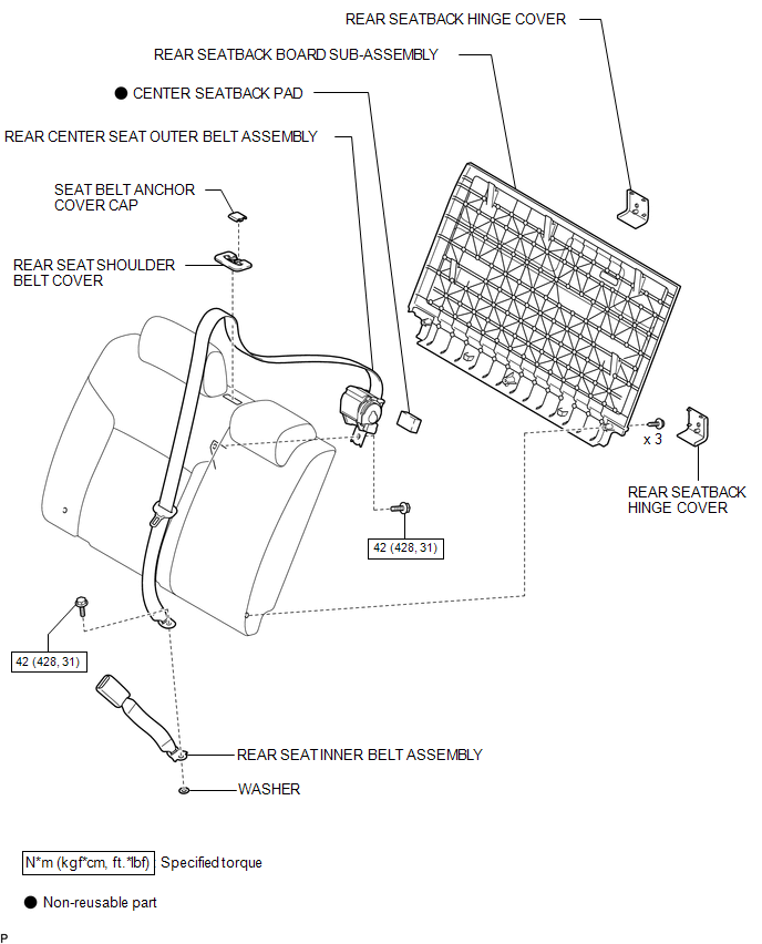
COMPONENTS
ILLUSTRATION
Removal
REMOVAL
PROCEDURE
1. REMOVE REAR SEATBACK HINGE COVER
.gif)
2. REMOVE REAR SEATBACK BOARD SUB-ASSEMBLY
3. REMOVE SEAT BELT ANCHOR COVER CAP
4. REMOVE REAR SEAT SHOULDER BELT COVER
5. REMOVE CENTER SEATBACK PAD
|
(a) Remove the center seatback pad. |
|
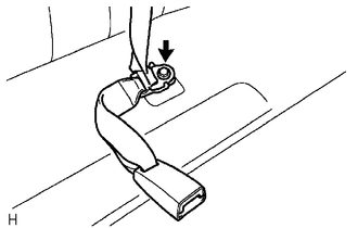
6. REMOVE REAR CENTER SEAT OUTER BELT ASSEMBLY
|
(a) Remove the bolt to disconnect the floor anchor of the rear center seat outer belt assembly and rear seat inner belt assembly. |
|
(b) Insert the belt through the hole into the rear seatback frame.
|
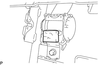
(c) Remove the bolt. |
|
(d) Disengage the 2 guides to remove the rear center seat outer belt assembly.
Installation
INSTALLATION
PROCEDURE
1. INSTALL REAR CENTER SEAT OUTER BELT ASSEMBLY
|
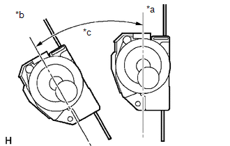
(a) Before installing the rear center seat outer belt assembly, check the ELR function. Text in Illustration
(1) When the inclination of the retractor is 15° or less, check that the belt can be pulled from the retractor. When the inclination of the retractor is over 45°, check that the belt locks. NOTICE: Do not disassemble the retractor. |
|
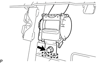
(b) Engage the 2 guides to install the rear center seat outer belt assembly with the bolt.
Torque:
42 N·m {428 kgf·cm, 31 ft·lbf}
(c) Insert the belt through the hole into the rear seatback frame.
|
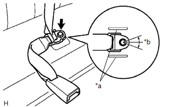
(d) Connect the rear seat inner belt assembly and rear center seat outer belt assembly by installing the floor anchor with the bolt. Text in Illustration
Torque: 42 N·m {428 kgf·cm, 31 ft·lbf} NOTICE:
|
|
2. INSTALL CENTER SEATBACK PAD
(a) Install a new center seatback pad.
3. INSTALL REAR SEAT SHOULDER BELT COVER
.gif)
4. INSTALL SEAT BELT ANCHOR COVER CAP
5. INSTALL REAR SEATBACK BOARD SUB-ASSEMBLY
6. INSTALL REAR SEATBACK HINGE COVER
 Disposal
DISPOSAL
CAUTION / NOTICE / HINT
CAUTION:
Before performing pre-disposal deployment of any SRS component, review and closely
follow all applicable environmental and hazardous material regulations ...
 Rear Seat Inner Belt Assembly(for Access Cab)
Components
COMPONENTS
ILLUSTRATION
Removal
REMOVAL
PROCEDURE
1. REMOVE REAR NO. 1 SEAT INNER BELT ASSEMBLY
(a) Open the 2 anchor covers.
(b) Loosen the 2 bolts to remove the 2 ...
Other materials:
Some Alarm Functions do not Operate
DESCRIPTION
When the alarm sounds, the following alarm functions operate: the roof console
box assembly and No. 1 room light assembly illuminates, and the headlights, taillights
and hazard lights flash, and the security horn and vehicle horn sound intermittently.
WIRING DIAGRAM
CAUTION / ...
Inspection
INSPECTION
PROCEDURE
1. INSPECT FUEL INJECTOR ASSEMBLY
NOTICE:
This inspection aims at inspecting the fuel injectors for opens or shorts, because
the fuel injectors of this vehicle are a high-pressure type and cannot be inspected
for fuel injection volume.
(a) Measure the resistance accordi ...
Headlight switch
The headlights can be operated manually.
Turning the end of the lever turns on the lights as follows:
Type A
The daytime running lights turn
on.
The side marker, parking, tail,
license plate, daytime running lights and instrument panel lights turn on.
The headlights and all lights lis ...
