Toyota Tacoma (2015-2018) Service Manual: Rear Seat Inner Belt Assembly(for Double Cab)
Installation
INSTALLATION
PROCEDURE
1. INSTALL REAR SEAT INNER BELT ASSEMBLY
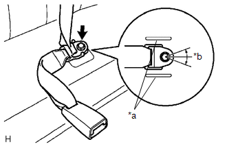
(a) for LH Side:
|
(1) Install the rear seat inner belt assembly with the bolt. Text in Illustration
Torque: 42 N·m {428 kgf·cm, 31 ft·lbf} NOTICE:
|
|
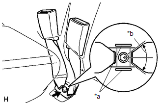
(b) for RH Side:
|
(1) Connect the rear seat inner belt assembly and rear center seat outer belt assembly by installing the floor anchor with the bolt. Text in Illustration
Torque: 42 N·m {428 kgf·cm, 31 ft·lbf} NOTICE:
|
|
Removal
REMOVAL
PROCEDURE
1. REMOVE REAR SEAT INNER BELT ASSEMBLY
(a) for LH Side:
|
(1) Remove the bolt and rear seat inner belt assembly. |
|
(b) for RH Side:
|
(1) Remove the bolt and rear seat inner belt assembly. |
|
.png)
 Rear Seat Inner Belt Assembly(for Access Cab)
Components
COMPONENTS
ILLUSTRATION
Removal
REMOVAL
PROCEDURE
1. REMOVE REAR NO. 1 SEAT INNER BELT ASSEMBLY
(a) Open the 2 anchor covers.
(b) Loosen the 2 bolts to remove the 2 ...

Other materials:
Removal
REMOVAL
PROCEDURE
1. REMOVE STEERING PAD
(See page )
2. REMOVE STEERING WHEEL ASSEMBLY
3. REMOVE LOWER STEERING COLUMN COVER
4. REMOVE UPPER STEERING COLUMN COVER
5. REMOVE SPIRAL CABLE SUB-ASSEMBLY WITH SENSOR
(a) Slide the slider and disconnect the airbag connector ...
Display does not Dim when Light Control Switch is Turned ON
PROCEDURE
1.
CHECK IMAGE QUALITY SETTING
(a) Display the "Display Settings" screen.
(b) Turn the light control switch to the tail or head position.
(c) Check if "Day Mode" on the display adjustment screen is on.
OK:
"Day Mode" sett ...
Diagnosis System
DIAGNOSIS SYSTEM
CHECK DLC3
(a) Check the DLC3.
Click here
FUNCTION OF WARNING INDICATOR AND MESSAGE
(a) If the lane departure alert system is not functioning properly, the driver
is warned by the lane departure alert indicator and multi-information display warning
message on the combinat ...
