Toyota Tacoma (2015-2018) Service Manual: Rear Differential Lock Solenoid Circuit Low (P17C0)
DESCRIPTION
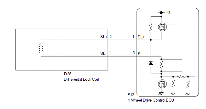
This DTC is output when a malfunction is detected due to a short to ground occurring in the differential lock coil drive circuit of the rear differential.
|
DTC No. |
Detection Item |
DTC Detection Condition |
Trouble Area |
|---|---|---|---|
|
P17C0 |
Rear Differential Lock Solenoid Circuit Low |
|
|
WIRING DIAGRAM
PROCEDURE
|
1. |
CHECK DIFFERENTIAL LOCK COIL |
(a) Disconnect the 4 wheel drive control ECU connector.
|
(b) Measure the resistance according to the value(s) in the table below. Standard Resistance:
|
|
| OK | .gif) |
REPLACE 4 WHEEL DRIVE CONTROL ECU |
|
.gif)
|
2. |
CHECK HARNESS AND CONNECTOR (4 WHEEL DRIVE CONTROL ECU - DIFFERENTIAL LOCK COIL) |
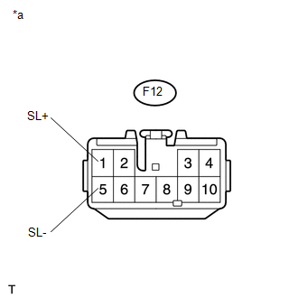
(a) Disconnect the F12 4 wheel drive control ECU connector.
(b) Disconnect the D28 differential lock coil connector.
(c) Measure the resistance according to the value(s) in the table below.
Standard Resistance:
|
Tester Connection |
Condition |
Specified Condition |
|---|---|---|
|
F12-1 (SL+) or D28-2 (SL+) - Body ground |
Always |
10 kΩ or higher |
|
F12-5 (SL-) or D28-1 (SL-) - Body ground |
Always |
10 kΩ or higher |
| OK | |
REPLACE DIFFERENTIAL LOCK COIL |
| NG | |
REPAIR OR REPLACE HARNESS OR CONNECTOR |
 Invalid Data Received from Vehicle Dynamics Control Module (U0416)
DESCRIPTION
This DTC is detected if a wheel speed malfunction signal is sent from the skid
control ECU (brake actuator assembly).
DTC No.
Detection Item
DTC Detect ...
 Rear Differential Lock Solenoid Circuit High (P17C1)
DESCRIPTION
This DTC is output when a malfunction is detected due to a battery short occurring
in the differential lock coil drive circuit of the rear differential.
DTC No.
D ...
Other materials:
Inspection
INSPECTION
PROCEDURE
1. INSPECT FRONT SHOCK ABSORBER ASSEMBLY
(a) Compress and extend the shock absorber rod and check that there is no abnormal
resistance or unusual sound during operation.
If there is any abnormality, replace the front shock absorber with a new one.
NOTICE:
When disposin ...
Front Radar Sensor Incorrect Axial Gap (C1A11,C1A14)
DESCRIPTION
When the system determines that the vehicle is driving straight ahead based on
signals from the yaw rate and acceleration sensor (airbag sensor assembly), etc.,
the millimeter wave radar sensor assembly performs self-diagnosis to check if the
sensor beam axis is misaligned.
C1A11 ...
Evaporator Temperature Sensor Circuit (B1413/13)
DESCRIPTION
The cooler thermistor sensor (evaporator temperature sensor) is installed on
the evaporator in the air conditioner unit to detect the temperature of the cooled
air that has passed through the evaporator and is used to control the air conditioning.
It sends signals to the air condi ...
