Toyota Tacoma (2015-2018) Service Manual: Disposal
DISPOSAL
CAUTION / NOTICE / HINT
CAUTION:
Before performing pre-disposal deployment of any SRS component, review and closely follow all applicable environmental and hazardous material regulations. Pre-disposal deployment may be considered hazardous material treatment.
PROCEDURE
1. PRECAUTION
- An airbag or pretensioner may be activated by static electricity. To prevent this, be sure to touch a metal surface with bare hands to discharge static electricity before performing this procedure.
- Never dispose of a front seat outer belt assembly that has an unactivated pretensioner.
- The seat belt pretensioner produces a loud, exploding sound when it activates. Perform the operation outside and where it will not be a nuisance to persons nearby.
- When activating a front seat outer belt assembly (with seat belt pretensioner), stand at least 10 m (32.8 ft.) away from the front seat outer belt assembly.
- When activating the seat belt pretensioner, always use the specified SST (SRS airbag deployment tool).
- The seat belt pretensioner becomes extremely hot when the front seat outer belt assembly is deployed, so do not touch it for at least 30 minutes after deployment.
- Use gloves and safety glasses when handling a front seat outer belt assembly with an activated pretensioner.
- Do not apply water, etc. to a front seat outer belt assembly that has an activated pretensioner.
- Always wash your hands with water after completing the activation.
HINT:
When scrapping vehicles equipped with a seat belt pretensioner or disposing of a front seat outer belt assembly (with a seat belt pretensioner), always deploy the seat belt pretensioner first in accordance with the procedure described below. If any abnormality occurs during deployment of the seat belt pretensioner, contact the service dept. of the distributor.
2. DISPOSE OF FRONT SEAT OUTER BELT ASSEMBLY (When Installed in Vehicle)
HINT:
Prepare a battery to power activation of the seat belt pretensioner.
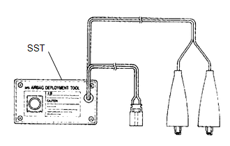
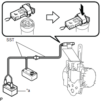
(a) Check whether SST is functioning.
 Text in Illustration
|
*a |
Battery |
SST: 09082-00700
SST: 09082-00770
CAUTION:
When deploying a seat belt pretensioner, always use the specified SST.
(1) Connect the red clip of SST to the positive (+) battery terminal and the black clip to the negative (-) battery terminal.
HINT:
At this time, do not connect the yellow connector. It will be connected to the seat belt pretensioner in a later step.
|
(2) Press the SST deployment switch and check that the LED of the SST deployment switch illuminates. CAUTION: If the LED is illuminated when the deployment switch is not pressed, SST may be malfunctioning. In this case, do not use the malfunctioning SST. |
|
(b) Disconnect SST from the battery.
(c) Disconnect the pretensioner connector.
(1) Disconnect the cable from the negative (-) battery terminal.
(2) Remove the front door scuff plate (See page
.gif) ).
).
(3) Remove the rear door scuff plate (See page
).
(4) Disconnect the front door opening trim weatherstrip (See page
).
(5) Disconnect the rear door opening trim weatherstrip (See page
).
(6) Remove the lap belt outer anchor cover (See page
).
(7) Remove the center pillar lower garnish (See page
).
(8) Connect the floor anchor with the bolt.
Torque:
42 N·m {428 kgf·cm, 31 ft·lbf}
|
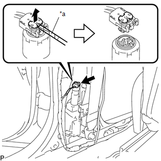
(9) Using a screwdriver with its tip wrapped in protective tape, release the locking button to disconnect the connector. Text in Illustration
|
|
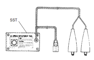
(d) Connect SST.
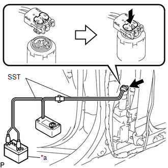 Text in Illustration
|
*a |
Battery |
(1) Connect 2 SST and then connect them to the seat belt pretensioner.
SST: 09082-00700
SST: 09082-00770
NOTICE:
Do not lock the secondary lock of the twin lock to avoid damaging the SST connector and wire harness.
|
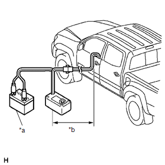
(2) Move SST at least 10 m (32.8 ft.) away from the front of the vehicle. Text in Illustration
|
|
(3) Close all the doors and windows of the vehicle.
HINT:
Do not damage the SST wire harness.
(4) Connect the red clip of SST to the positive (+) battery terminal and the black clip to the negative (-) battery terminal.
(e) Deploy the seat belt pretensioner.
(1) Confirm that no one is inside the vehicle or within a 10 m (32.8 ft.) radius of the vehicle.
(2) Press the SST deployment switch to deploy the seat belt pretensioner.
HINT:
The seat belt pretensioner will deploy at the same time as the LED of SST illuminates.
(f) Dispose of the front seat outer belt assembly.
CAUTION:
- The front seat outer belt assembly becomes very hot when the pretensioner is deployed, so leave it untouched for at least 30 minutes after the pretensioner is deployed.
- Use gloves and safety glasses when handling a front seat outer belt assembly with a deployed pretensioner.
- Always wash your hands with water after completing the operation.
- Do not apply water, etc. to a front seat outer belt assembly with a deployed pretensioner.
HINT:
When scrapping a vehicle, deploy the seat belt pretensioner, and then scrap the vehicle with the front seat outer belt assembly installed.
3. DISPOSE OF FRONT SEAT OUTER BELT ASSEMBLY (When not Installed in Vehicle)
CAUTION:
- Use gloves and safety glasses when handling a front seat outer belt assembly with a deployed pretensioner.
- Always wash your hands with water after completing the operation.
- Do not apply water, etc. to a front seat outer belt assembly with a deployed pretensioner.
- When deploying a seat belt pretensioner, always use the specified SST (SRS airbag deployment tool). Perform the operation in a place away from electrical interference.
NOTICE:
- When disposing of a front seat outer belt assembly with a pretensioner, never deploy the seat belt pretensioner in the customer's vehicle.
- Never dispose of a front seat outer belt assembly with a pretensioner that has not been deployed.
- The front seat outer belt assembly produces an exploding sound when the pretensioner deploys, so perform the operation outdoors and where it will not disturb local residents.
- When deploying a seat belt pretensioner, perform the operation at least 10 m (32.8 ft.) away from the front seat outer belt assembly.
- Be sure to follow the procedure listed below when deploying a seat belt pretensioner.
(a) Remove the front seat outer belt assembly (See page
).
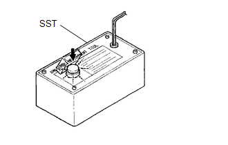
(b) Wind the front seat outer belt assembly webbing with the retractor.
|
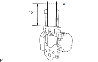
(c) When the front seat outer belt assembly webbing is sufficiently wound, cut the front seat outer belt assembly webbing approximately 100 mm (3.94 in.) from the retractor, as shown in the illustration. Text in Illustration
HINT: The retractor resistance increases in correlation with how much the front seat outer belt assembly webbing is wound. |
|
|
(d) Check whether SST is functioning (see step 2-(a)). Text in Illustration
SST: 09082-00700 SST: 09082-00770 CAUTION: When deploying the seat belt pretensioner, always use the specified SST. |
|

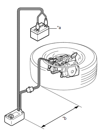
(e) Connect SST.
 Text in Illustration
|
*a |
Battery |
(1) Connect 2 SST and then connect them to the seat belt pretensioner.
NOTICE:
Do not lock the secondary lock of the twin lock to avoid damaging the SST connector and wire harness.
|
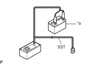
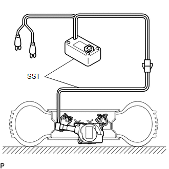
(2) Place the front seat outer belt assembly on the ground and cover it with a tire and disc wheel. NOTICE:
|
|
|
(3) Position and hold SST at least 10 m (32.8 ft.) away from the disc wheel. Text in Illustration
NOTICE: Do not damage the SST wire harness. |
|
(f) Deploy the seat belt pretensioner.
(1) Check that no one is within a 10 m (32.8 ft.) radius of the disc wheel.
(2) Connect the red clip of SST to the positive (+) battery terminal and the black clip to the negative (-) battery terminal.
(3) Press the SST deployment switch to deploy the seat belt pretensioner.
HINT:
The seat belt pretensioner will deploy at the same time as the LED of SST illuminates.
(g) Dispose of the front seat outer belt assembly.
CAUTION:
- The front seat outer belt assembly becomes very hot when the pretensioner is deployed, so leave it untouched for at least 30 minutes after the pretensioner is deployed.
- Use gloves and safety glasses when handling a front seat outer belt assembly with a deployed pretensioner.
- Always wash your hands with water after completing the operation.
- Do not apply water, etc. to a front seat outer belt assembly with a deployed pretensioner.
 Removal
REMOVAL
CAUTION / NOTICE / HINT
HINT:
Use the same procedure for both the RH and LH sides.
The procedure described below is for the LH side.
PROCEDURE
1. PRECAUTION
NOTICE:
Af ...
 Rear Center Seat Outer Belt Assembly(for Double Cab)
Components
COMPONENTS
ILLUSTRATION
Removal
REMOVAL
PROCEDURE
1. REMOVE REAR SEATBACK HINGE COVER
2. REMOVE REAR SEATBACK BOARD SUB-ASSEMBLY
3. REMOVE SEAT BELT ANCHOR COVER CAP
...
Other materials:
Open in Bus 5 Main Bus Line
DESCRIPTION
There may be an open circuit in one of the CAN main bus lines when the resistance
between terminals 15 (CA5H) and 16 (CA5L) of the central gateway ECU (network gateway
ECU) is 70 Ω or higher.
Detection Item
Trouble Area
Resistance between ter ...
Terminals Of Ecu
TERMINALS OF ECU
1. MOBILE WIRELESS CHARGER CRADLE ASSEMBLY
Tester Connection
Wiring Color
Terminal Description
Condition
Specified Condition
M5-1 (ACC) - M5-5 (PGND)
GR - W-B
Power source (ACC)
...
Steering Pad Switch Circuit
DESCRIPTION
This circuit sends an operation signal from the steering pad switch assembly
to the navigation receiver assembly.
If there is an open in the circuit, the audio system cannot be operated using
the steering pad switch assembly.
If there is a short in the circuit, the same condition ...
