Toyota Tacoma (2015-2018) Service Manual: Radio Broadcast cannot be Received or Poor Reception
PROCEDURE
|
1. |
CHECK RADIO AND DISPLAY RECEIVER ASSEMBLY |
(a) Check the radio automatic station search function.
(1) Check the radio automatic station search function by activating it.
Result|
Result |
Proceed to |
|---|---|
|
Automatic station search function does not stop |
A |
|
Automatic station search function stops on a station |
B |
| B | .gif) |
REPLACE RADIO AND DISPLAY RECEIVER ASSEMBLY |
|
.gif)
|
2. |
CHECK OPTIONAL COMPONENTS |
(a) Check if any optional components that may decrease reception capacity, such as sunshade film or a telephone antenna, are installed.
Result|
Result |
Proceed to |
|---|---|
|
Optional components are not installed |
A |
|
Optional components are installed |
B |
NOTICE:
Do not remove optional components without the permission of the customer.
| B | |
REMOVE OPTIONAL COMPONENTS AND CHECK AGAIN (SEE NOTICE ABOVE) |
|
|
3. |
CHECK RADIO AND DISPLAY RECEIVER ASSEMBLY |
|
(a) Preparation for check (1) Remove the antenna connector from the radio and display receiver assembly. |
|
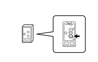
(b) Check for noise
(1) Turn the ignition switch to ACC with the radio and display receiver assembly connector connected.
(2) Turn the radio on and tune into AM mode.
(3) Place a screwdriver, thin wire or other metal object on the radio and display receiver assembly antenna jack and check that noise can be heard from the speakers.
OK:
Noise can be heard from the speakers.
| NG | |
REPAIR RADIO AND DISPLAY RECEIVER ASSEMBLY |
|
|
4. |
INSPECT RADIO AND DISPLAY RECEIVER ASSEMBLY |
|
(a) Disconnect the radio and display receiver assembly connector. |
|
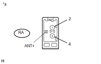
(b) Measure the voltage according to the value(s) in the table below.
Standard Voltage:
|
Tester Connection |
Switch Condition |
Specified Condition |
|---|---|---|
|
RA-5 (ANT+) - Body ground |
Ignition switch ACC Radio switch on and FM or AM selected |
11 to 14 V |
|
*a |
Component without harness connected (Radio and Display Receiver Assembly) |
| NG | |
REPLACE RADIO AND DISPLAY RECEIVER ASSEMBLY |
|
|
5. |
REPLACE ANTENNA CORD SUB-ASSEMBLY |
(a) Replace the antenna cord sub-assembly and check if radio broadcasts can be
received normally (See page .gif) ).
).
OK:
Radio broadcasts can be received normally.
| OK | |
END |
|
|
6. |
REPLACE NO. 2 ANTENNA CORD SUB-ASSEMBLY |
(a) Replace the No. 2 antenna cord sub-assembly with a new or known good one
and check if radio broadcasts can be received normally (See page
).
OK:
Radio broadcasts can be received normally.
| OK | |
END |
|
|
7. |
REPLACE ANTENNA ASSEMBLY WITH HOLDER |
(a) Replace the antenna assembly with holder and check if radio broadcasts can
be received normally (See page ).
OK:
Radio broadcasts can be received normally.
| OK | |
END |
| NG | |
REPLACE RADIO AND DISPLAY RECEIVER ASSEMBLY |
 CD Sound Skips
PROCEDURE
1.
CHECK CD
(a) Check that the CD is not deformed or cracked.
OK:
No deformation or cracks on the CD
...
 Illumination for Panel Switch does not Come on with Tail Switch ON
PROCEDURE
1.
CHECK VEHICLE SIGNAL (OPERATION CHECK)
(a) Enter the "Vehicle Signal Check Mode" screen. Refer to Check Vehicle Signal
in Operation Check (Se ...
Other materials:
Air Conditioning Amplifier
Components
COMPONENTS
ILLUSTRATION
Installation
INSTALLATION
PROCEDURE
1. INSTALL AIR CONDITIONING AMPLIFIER ASSEMBLY
(a) Install the air conditioner amplifier assembly with the 2 bolts.
Torque:
7.0 N·m {71 kgf·cm, 62 in·lbf}
(b) Connect the 2 connectors.
2. INSTALL INSTRUMENT L ...
Installation
INSTALLATION
PROCEDURE
1. INSTALL FRONT NO. 2 SPEAKER ASSEMBLY RH
(a) Connect the connector.
(b) Install the front No. 2 speaker assembly RH with the 2 bolts.
Torque:
8.4 N·m {86 kgf·cm, 74 in·lbf}
NOTICE:
Do not touch the cone part of the front No. 2 speaker assembly RH.
...
Components
COMPONENTS
ILLUSTRATION
*A
for Driver Side
-
-
*1
FRONT SEAT CUSHION HEATER ASSEMBLY
*2
SEPARATE TYPE FRONT SEAT CUSHION COVER
*3
TAG PIN
-
-
...
