Toyota Tacoma (2015-2018) Service Manual: Illumination for Panel Switch does not Come on with Tail Switch ON
PROCEDURE
|
1. |
CHECK VEHICLE SIGNAL (OPERATION CHECK) |
(a) Enter the "Vehicle Signal Check Mode" screen. Refer to Check Vehicle Signal
in Operation Check (See page .gif) ).
).
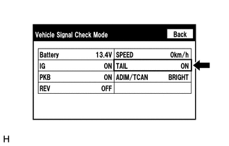
(b) Check that the display changes between ON and OFF according to the light control switch operation.
OK:
|
Light Control Switch |
Display |
|---|---|
|
Tail or head |
ON |
|
Off |
OFF |
HINT:
This display is updated once per second. As a result, it is normal for the display to lag behind the actual switch operation.
| OK | .gif) |
REPLACE RADIO AND DISPLAY RECEIVER ASSEMBLY |
| NG | |
PROCEED TO NEXT SUSPECTED AREA SHOWN IN PROBLEM SYMPTOMS TABLE |
 Radio Broadcast cannot be Received or Poor Reception
PROCEDURE
1.
CHECK RADIO AND DISPLAY RECEIVER ASSEMBLY
(a) Check the radio automatic station search function.
(1) Check the radio automatic station search function b ...
 Display does not Dim when Light Control Switch is Turned ON
PROCEDURE
1.
CHECK IMAGE QUALITY SETTING
(a) Display the "Display" screen.
(b) Turn the light control switch to the tail or head position.
(c) Check if &q ...
Other materials:
Door Control Receiver
Components
COMPONENTS
ILLUSTRATION
Removal
REMOVAL
PROCEDURE
1. REMOVE ROOF HEADLINING ASSEMBLY (for Double Cab)
(See page )
2. REMOVE ROOF HEADLINING ASSEMBLY (for Access Cab)
(See page )
3. REMOVE DOOR CONTROL RECEIVER (w/o Tire Pressure Warning System)
(a) Disconne ...
Inspection
INSPECTION
PROCEDURE
1. INSPECT RADIATOR CORE SUB-ASSEMBLY
Check the core plate for damage.
Text in Illustration
*1
Core Plate
*2
Radiator Core
If the sides of the core plate groove are deformed, it is impossible
to reassem ...
Power Source Circuit
DESCRIPTION
This circuit provides power to operate the forward recognition camera.
WIRING DIAGRAM
CAUTION / NOTICE / HINT
NOTICE:
Inspect the fuses for circuits related to this system before performing the following
inspection procedure.
PROCEDURE
1.
CHECK HARNESS A ...
