Toyota Tacoma (2015-2018) Service Manual: Radio Receiver
Components
COMPONENTS
ILLUSTRATION
ILLUSTRATION
Removal
REMOVAL
PROCEDURE
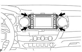
1. REMOVE INSTRUMENT CLUSTER CENTER FINISH PANEL SUB-ASSEMBLY
(See page .gif) )
)
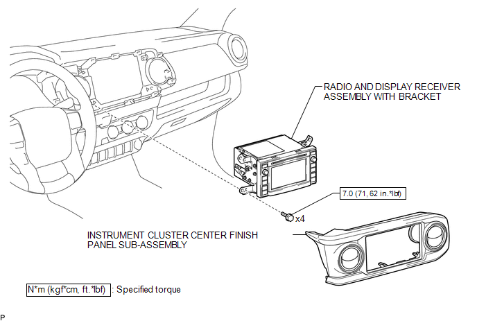
2. REMOVE RADIO AND DISPLAY RECEIVER ASSEMBLY WITH BRACKET
|
(a) Remove the 4 bolts. |
|
(b) Disconnect the connectors to remove the radio and display receiver assembly with bracket.
3. REMOVE NO. 1 NAVIGATION WIRE (w/ Satellite Radio)
(See page )
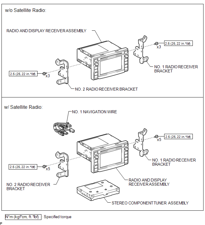
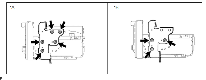
4. REMOVE NO. 1 RADIO RECEIVER BRACKET
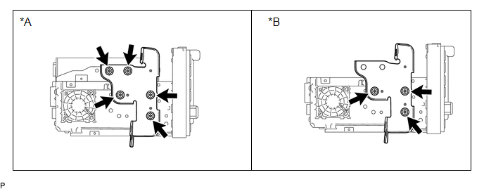 Text in Illustration
|
*A |
w/ Satellite Radio |
*B |
w/o Satellite Radio |
(a) w/ Satellite Radio:
Remove the 5 bolts and No. 1 radio receiver bracket.
(b) w/o Satellite Radio:
Remove the 3 bolts and No. 1 radio receiver bracket.
5. REMOVE NO. 2 RADIO RECEIVER BRACKET
 Text in Illustration
|
*A |
w/ Satellite Radio |
*B |
w/o Satellite Radio |
(a) w/ Satellite Radio:
Remove the 5 bolts and No. 2 radio receiver bracket.
(b) w/o Satellite Radio:
Remove the 3 bolts and No. 2 radio receiver bracket.
6. REMOVE STEREO COMPONENT TUNER ASSEMBLY (w/ Satellite Radio)
(See page )
Installation
INSTALLATION
PROCEDURE
1. INSTALL STEREO COMPONENT TUNER ASSEMBLY (w/ Satellite Radio)
(See page .gif) )
)
2. INSTALL NO. 2 RADIO RECEIVER BRACKET
(a) w/ Satellite Radio:
Install the No. 2 radio receiver bracket with the 5 bolts.
Torque:
2.5 N·m {25 kgf·cm, 22 in·lbf}
(b) w/o Satellite Radio:
Install the No. 2 radio receiver bracket with the 3 bolts.
Torque:
2.5 N·m {25 kgf·cm, 22 in·lbf}
3. INSTALL NO. 1 RADIO RECEIVER BRACKET
(a) w/ Satellite Radio:
Install the No. 1 radio receiver bracket with the 5 bolts.
Torque:
2.5 N·m {25 kgf·cm, 22 in·lbf}
(b) w/o Satellite Radio:
Install the No. 1 radio receiver bracket with the 3 bolts.
Torque:
2.5 N·m {25 kgf·cm, 22 in·lbf}
4. INSTALL NO. 1 NAVIGATION WIRE (w/ Satellite Radio)
(See page )
5. INSTALL RADIO AND DISPLAY RECEIVER ASSEMBLY WITH BRACKET
(a) Connect the connectors.
(b) Install the radio and display receiver assembly with bracket with the 4 bolts.
Torque:
7.0 N·m {71 kgf·cm, 62 in·lbf}
6. INSTALL INSTRUMENT CLUSTER CENTER FINISH PANEL SUB-ASSEMBLY
(See page )
 Radio Antenna Cord
Components
COMPONENTS
ILLUSTRATION
Removal
REMOVAL
PROCEDURE
1. REMOVE INSTRUMENT PANEL SUB-ASSEMBLY
(See page )
2. REMOVE ANTENNA CORD SUB-ASSEMBLY
(a) Disengage the 4 clamps to remo ...

Other materials:
Distance Control Switch Circuit
DESCRIPTION
The distance control switch is used to set the distance for vehicle-to-vehicle
distance control mode. The distance control switch is installed in the steering
pad switch assembly. The vehicle-to-vehicle distance set value can be changed by
operating the steering pad switch assembl ...
Disassembly
DISASSEMBLY
PROCEDURE
1. REMOVE SHIFT LOCK RELEASE BUTTON COVER
(a) Using a screwdriver with its tip wrapped in protective tape, detach the 2
claws to remove the shift lock release button cover from the console upper panel
sub-assembly.
Text in Illustration
*a
Protect ...
How To Proceed With Troubleshooting
CAUTION / NOTICE / HINT
HINT:
Use these procedures to troubleshoot the smart key system (for Entry
Function).
*: Use the Techstream.
PROCEDURE
1.
VEHICLE BROUGHT TO WORKSHOP
NEXT
...
