Toyota Tacoma (2015-2018) Service Manual: Ptc Heater Relay
Components
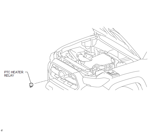
COMPONENTS
ILLUSTRATION
Inspection
INSPECTION
PROCEDURE
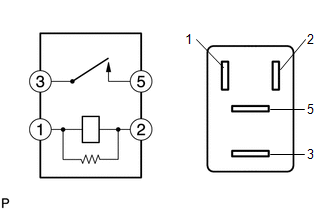
1. INSPECT PTC HEATER RELAY
(a) Check the resistance.
|
(1) Measure the resistance according to the value(s) in the table below. Standard Resistance:
If the result is not as specified, replace the ptc heater relay. |
|
Installation
INSTALLATION
PROCEDURE
1. INSTALL PTC HEATER RELAY
(a) Install the ptc heater relay.
Removal
REMOVAL
PROCEDURE
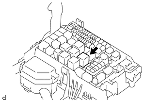
1. REMOVE PTC HEATER RELAY
|
(a) Remove the ptc heater relay. |
|
 Ptc Heater Assembly
Components
COMPONENTS
ILLUSTRATION
Removal
REMOVAL
PROCEDURE
1. REMOVE LOWER NO. 2 INSTRUMENT PANEL AIRBAG ASSEMBLY
(See page )
2. REMOVE INSTRUMENT LOWER PANEL ASSEMBLY
3. REMOVE ...
 Refrigerant Line
Components
COMPONENTS
ILLUSTRATION
...
Other materials:
Invalid Data Received From Vehicle Dynamics Control Module (U0416)
DESCRIPTION
This DTC is detected if a wheel speed malfunction signal is sent from the skid
control ECU (brake actuator assembly).
DTC No.
Detection Item
DTC Detection Condition
Trouble Area
U0416
Invalid Data Received From V ...
Installation
INSTALLATION
PROCEDURE
1. INSTALL INTAKE MANIFOLD
(a) Set 2 new No. 1 intake manifold to head gaskets on cylinder head
sub-assembly and cylinder head LH as shown in the illustration.
NOTICE:
Align the port holes of the gasket and cylinder head sub-assembly
...
Lost Communication With Image Processing Module "A" (U023A)
DESCRIPTION
The millimeter wave radar sensor assembly communicates with the forward recognition
camera via CAN communication. If there is a communication error with the forward
recognition camera, the millimeter wave radar sensor assembly stores DTC U023A.
DTC No.
Detecti ...
