Toyota Tacoma (2015-2018) Service Manual: Ptc Heater Assembly
Components
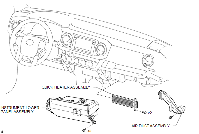
COMPONENTS
ILLUSTRATION
Removal
REMOVAL
PROCEDURE
1. REMOVE LOWER NO. 2 INSTRUMENT PANEL AIRBAG ASSEMBLY
(See page .gif) )
)
2. REMOVE INSTRUMENT LOWER PANEL ASSEMBLY
3. REMOVE AIR DUCT ASSEMBLY
4. REMOVE QUICK HEATER ASSEMBLY
|
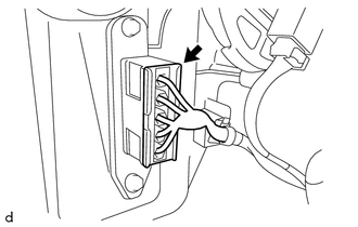
(a) Disconnect the connector. |
|
|
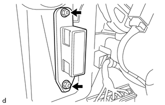
(b) Remove the 2 screws and quick heater assembly. |
|
Inspection
INSPECTION
PROCEDURE
1. INSPECT QUICK HEATER ASSEMBLY
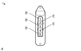
(a) Check the resistance.
|
(1) Measure the resistance according to the value(s) in the table below. Text in Illustration
Standard Resistance:
If the specified condition is not met, replace the quick heater assembly. |
|
Installation
INSTALLATION
PROCEDURE
1. INSTALL QUICK HEATER ASSEMBLY
(a) Install the quick heater assembly with the 2 screws.
(b) Connect the connector.
2. INSTALL AIR DUCT ASSEMBLY
.gif)
3. INSTALL INSTRUMENT LOWER PANEL ASSEMBLY
4. INSTALL LOWER NO. 2 INSTRUMENT PANEL AIRBAG ASSEMBLY
(See page )
 Magnetic Clutch Relay
Inspection
INSPECTION
PROCEDURE
1. INSPECT MAGNET-CLUTCH RELAY
(a) Check the resistance.
(1) Using an ohmmeter, measure the resistance between the terminals.
Standard:
...
 Ptc Heater Relay
Components
COMPONENTS
ILLUSTRATION
Inspection
INSPECTION
PROCEDURE
1. INSPECT PTC HEATER RELAY
(a) Check the resistance.
(1) Measure the resistance according to the value(s) i ...
Other materials:
Problem Symptoms Table
PROBLEM SYMPTOMS TABLE
HINT:
Use the table below to help determine the cause of problem symptoms.
If multiple suspected areas are listed, the potential causes of the symptoms
are listed in order of probability in the "Suspected Area" column of the
table. Check each sy ...
Disassembly
DISASSEMBLY
PROCEDURE
1. REMOVE INTAKE VALVE
(a) Using SST, compress the inner compression spring and remove the valve
spring retainer locks.
SST: 09202-70020
SST: 09202-00021
09202-01010
09202-01020
(b) Remove the valve s ...
Disassembly
DISASSEMBLY
PROCEDURE
1. REMOVE SHIFT LOCK RELEASE BUTTON COVER
(a) Using a screwdriver with its tip wrapped in protective tape, detach the 2
claws to remove the shift lock release button cover from the console upper panel
sub-assembly.
Text in Illustration
*a
Protect ...
