Toyota Tacoma (2015-2018) Service Manual: Pcv Valve
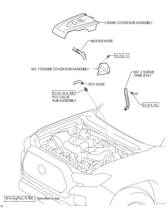
Components
COMPONENTS
ILLUSTRATION
Inspection
INSPECTION
PROCEDURE
1. INSPECT PCV VALVE SUB-ASSEMBLY
(a) Install a clean hose to the PCV valve sub-assembly.
(b) Check the PCV valve sub-assembly operation.
(1) Blow air into the cylinder head cover sub-assembly LH side and check that air passes through easily. If the result is not as specified, replace the PCV valve sub-assembly.
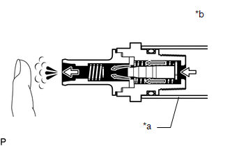 Text in Illustration
|
*a |
Clean Hose |
|
*b |
Cylinder Head Cover Sub-assembly LH Side |
.png) |
Air |
If the result is not as specified, replace the PCV valve sub-assembly.
CAUTION:
Do not suck air through the valve. Petroleum substances inside the valve are hazardous to your health.
(2) Blow air into the intake air surge tank side and check that air passes through with difficulty.
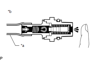 Text in Illustration
|
*a |
Clean Hose |
|
*b |
Intake Air Surge Tank Side |
|
|
Air |
If the result is not as specified, replace the PCV valve sub-assembly.
(c) Remove the clean hose from the PCV valve sub-assembly.
Removal
REMOVAL
PROCEDURE
1. REMOVE V-BANK COVER SUB-ASSEMBLY
.gif)
2. REMOVE NO. 2 SURGE TANK STAY
3. DISCONNECT HEATER HOSE
|
(a) Disengage the clamp and disconnect the heater hose. |
|
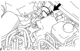
4. DISCONNECT PCV HOSE
|
(a) Slide the clip and disconnect the PCV hose from the cylinder head cover sub-assembly LH. |
|
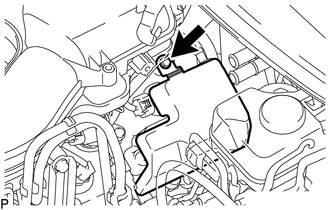
5. REMOVE NO. 1 ENGINE COVER SUB-ASSEMBLY
|
(a) Remove the bolt and No. 1 engine cover sub-assembly from the cylinder head cover sub-assembly LH. |
|
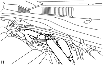
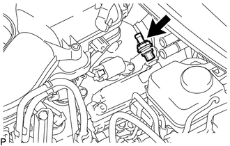
6. REMOVE PCV VALVE SUB-ASSEMBLY
|
(a) Remove the PCV valve sub-assembly from the cylinder head cover sub-assembly LH. |
|
Installation
INSTALLATION
PROCEDURE
1. INSTALL PCV VALVE SUB-ASSEMBLY
(a) Apply a light coat of engine oil to the O-ring.
(b) Install the PCV valve sub-assembly to the cylinder head cover sub-assembly LH.
Torque:
5.0 N·m {51 kgf·cm, 44 in·lbf}
NOTICE:
When reusing the PCV valve sub-assembly, inspect the O-ring.
2. INSTALL NO. 1 ENGINE COVER SUB-ASSEMBLY
(a) Install the No. 1 engine cover sub-assembly with the bolt to the cylinder head cover sub-assembly LH.
Torque:
10 N·m {102 kgf·cm, 7 ft·lbf}
3. CONNECT PCV HOSE
(a) Connect the PCV hose to the cylinder head cover sub-assembly LH, and slide the clip to secure the hose.
4. CONNECT HEATER HOSE
(a) Engage the clamp and connect the heater hose.
5. INSTALL NO. 2 SURGE TANK STAY
.gif)
6. INSTALL V-BANK COVER SUB-ASSEMBLY
 Fuel Tank Cap
Inspection
INSPECTION
PROCEDURE
1. INSPECT FUEL TANK CAP ASSEMBLY
(a) Check the appearance of the fuel tank cap assembly.
(1) Check that there is no deformation or damage to the fuel tank cap a ...
 Purge Valve
Components
COMPONENTS
ILLUSTRATION
Inspection
INSPECTION
PROCEDURE
1. INSPECT PURGE VSV
(a) Measure the resistance according to the value(s) in the table below.
Text in Illu ...
Other materials:
Hydraulic Test
HYDRAULIC TEST
1. PERFORM HYDRAULIC TEST
(a) Measure the line pressure.
CAUTION:
The line pressure test should always be performed with at least 2 people. One
person should observe the condition of the wheels and wheel chocks while the other
is performing the test.
NOTICE:
Perform ...
On-vehicle Inspection
ON-VEHICLE INSPECTION
PROCEDURE
1. INSPECT CAMSHAFT TIMING OIL CONTROL SOLENOID ASSEMBLY (for Intake Side)
(a) Connect the Techstream to the DLC3.
(b) Start the engine.
(c) Turn the Techstream on.
(d) Enter the following menus: Powertrain / Engine / Active Test / Control the
Intake VVT OCV D ...
Freeze Frame Data
FREEZE FRAME DATA
1. FREEZE FRAME DATA
HINT:
Whenever a DTC is detected or the ABS operates, the skid control ECU
stores the current vehicle (sensor) state as freeze frame data.
The skid control ECU stores the number of times (maximum: 31) the ignition
switch has been turned f ...
