Toyota Tacoma (2015-2018) Service Manual: Power Window Switch Malfunction (B2312)
DESCRIPTION
The power window regulator motor assembly is operated by the power window regulator master switch assembly or power window regulator switch assembly. The power window regulator motor assembly has motor, regulator and ECU functions.
This DTC is output when the ECU built into the regulator motor determines that the power window regulator master switch assembly or power window regulator switch assembly is stuck.
HINT:
DTC B2312 can be stored in the power window regulator master switch assembly and in each power window regulator motor assembly (power window ECU).
Master Switch|
DTC No. |
DTC Detection Condition |
Trouble Area |
|---|---|---|
|
B2312 |
|
Power window regulator master switch assembly |
|
DTC No. |
DTC Detection Condition |
Trouble Area |
|---|---|---|
|
B2312 |
|
|
|
DTC No. |
DTC Detection Condition |
Trouble Area |
|---|---|---|
|
B2312 |
|
|
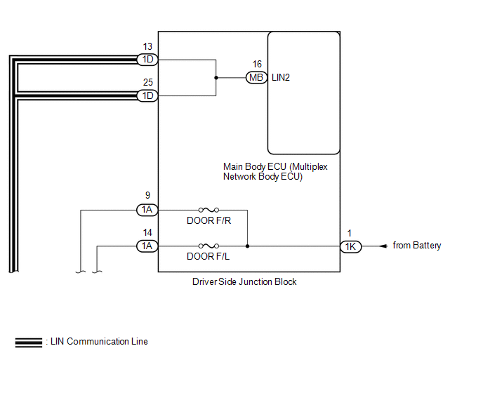
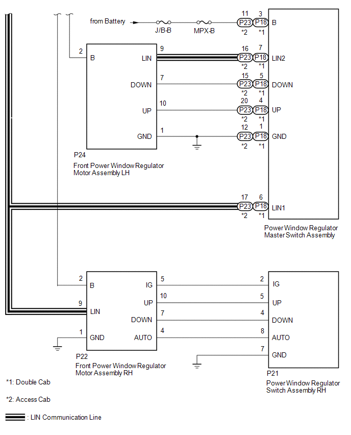
WIRING DIAGRAM
CAUTION / NOTICE / HINT
NOTICE:
- DTC B2312 is stored in the power window regulator master switch assembly and in each power window regulator motor assembly.
- If a power window regulator motor assembly has been replaced with a
new one, initialize the power window control system (See page
.gif) ).
). - Inspect the fuses for circuits related to this system before performing the following procedure.
- The power window control system uses the LIN communication system. Inspect
the communication function by following How to Proceed with Troubleshooting.
Troubleshoot the power window control system after confirming that the communication
system is functioning properly (See page
).
PROCEDURE
|
1. |
CHECK DTC OUTPUT |
(a) Clear the DTC (See page ).
(b) Check for DTCs (See page ).
OK:
No DTCs output.
| OK | .gif) |
END (DUE TO SWITCH BEING OPERATED FOR 20 SECONDS OR MORE) |
|
.gif)
|
2. |
CHECK DTC OUTPUT |
(a) Check for DTC output conditions.
Result|
Result |
Proceed to |
|---|---|
|
DTC output from power window regulator master switch assembly |
A |
|
DTC output from front power window regulator motor assembly LH |
B |
|
DTC output from front power window regulator motor assembly RH |
C |
| A | |
REPLACE POWER WINDOW REGULATOR MASTER SWITCH ASSEMBLY |
| C | |
GO TO STEP 7 |
|
|
3. |
READ VALUE USING TECHSTREAM (D-DOOR MOTOR) |
(a) Connect the Techstream to the DLC3.
(b) Turn the ignition switch to ON.
(c) Turn the Techstream on.
(d) Enter the following menus: Body Electrical / D-Door Motor / Data List.
(e) Read the Data List according to the display on the Techstream.
D-Door Motor (Front Power Window Regulator Motor Assembly LH)|
Tester Display |
Measurement Item/Range |
Normal Condition |
Diagnostic Note |
|---|---|---|---|
|
D Door P/W Up SW |
Driver side power window manual up switch signal / ON or OFF |
ON: Driver side power window manual up switch operated OFF: Driver side power window manual up switch not operated |
- |
|
D Door P/W Down SW |
Driver side power window manual down switch signal / ON or OFF |
ON: Driver side power window manual down switch operated OFF: Driver side power window manual down switch not operated |
- |
OK:
On the Techstream screen, ON or OFF is displayed accordingly.
| OK | |
REPLACE FRONT POWER WINDOW REGULATOR MOTOR ASSEMBLY LH |
|
|
4. |
CHECK HARNESS AND CONNECTOR (POWER WINDOW REGULATOR MASTER SWITCH ASSEMBLY - FRONT POWER WINDOW REGULATOR MOTOR ASSEMBLY LH) |
(a) for Double Cab:
(1) Disconnect the P18 power window regulator master switch assembly connector.
(2) Disconnect the P24 front power window regulator motor assembly LH connector.
(3) Measure the resistance according to the value(s) in the table below.
Standard Resistance:
|
Tester Connection |
Condition |
Specified Condition |
|---|---|---|
|
P18-4 (UP) - Body ground |
Always |
10 kΩ or higher |
|
P18-5 (DOWN) - Body ground |
Always |
10 kΩ or higher |
|
P24-10 (UP) - Body ground |
Always |
10 kΩ or higher |
|
P24-7 (DOWN) - Body ground |
Always |
10 kΩ or higher |
(b) for Access Cab:
(1) Disconnect the P23 power window regulator master switch assembly connector.
(2) Disconnect the P24 front power window regulator motor assembly LH connector.
(3) Measure the resistance according to the value(s) in the table below.
Standard Resistance:
|
Tester Connection |
Condition |
Specified Condition |
|---|---|---|
|
P23-20 (UP) - Body ground |
Always |
10 kΩ or higher |
|
P23-15 (DOWN) - Body ground |
Always |
10 kΩ or higher |
|
P24-10 (UP) - Body ground |
Always |
10 kΩ or higher |
|
P24-7 (DOWN) - Body ground |
Always |
10 kΩ or higher |
| NG | |
REPAIR OR REPLACE HARNESS OR CONNECTOR |
|
|
5. |
REPLACE POWER WINDOW REGULATOR MASTER SWITCH ASSEMBLY |
(a) Replace the power window regulator master switch assembly (See page
).
|
|
6. |
CHECK DTC OUTPUT |
(a) Clear the DTCs (See page ).
(b) Check for DTCs (See page ).
OK:
DTC B2312 is not output.
| OK | |
END (POWER WINDOW REGULATOR MASTER SWITCH ASSEMBLY WAS DEFECTIVE) |
| NG | |
REPLACE FRONT POWER WINDOW REGULATOR MOTOR ASSEMBLY LH |
|
7. |
READ VALUE USING TECHSTREAM (P-DOOR MOTOR) |
(a) Connect the Techstream to the DLC3.
(b) Turn the ignition switch to ON.
(c) Turn the Techstream on.
(d) Enter the following menus: Body Electrical / P-Door Motor / Data List.
(e) Read the Data List according to the display on the Techstream.
P-Door Motor (Front Power Window Regulator Motor Assembly RH)|
Tester Display |
Measurement Item/Range |
Normal Condition |
Diagnostic Note |
|---|---|---|---|
|
P Door P/W Auto SW |
Front passenger side power window auto up/down switch signal / ON or OFF |
ON: Front passenger side power window auto switch operated OFF: Front passenger side power window auto switch not operated |
- |
|
P Door P/W Up SW |
Front passenger side power window manual up switch signal / ON or OFF |
ON: Front passenger side power window manual up switch operated OFF: Front passenger side power window manual up switch not operated |
- |
|
P Door P/W Down SW |
Front passenger side power window manual down switch signal / ON or OFF |
ON: Front passenger side power window manual down switch operated OFF: Front passenger side power window manual down switch not operated |
- |
OK:
On the Techstream screen, ON or OFF is displayed accordingly.
| OK | |
REPLACE FRONT POWER WINDOW REGULATOR MOTOR ASSEMBLY RH |
|
|
8. |
INSPECT FRONT POWER WINDOW REGULATOR SWITCH ASSEMBLY RH |
(a) Remove the front power window regulator switch assembly RH (See page
).
(b) Inspect the front power window regulator switch assembly RH.
(1) Measure the resistance according to the value(s) in the table below.
Standard Resistance:
|
Tester Connection |
Switch Condition |
Specified Condition |
|---|---|---|
|
5 - 7 |
Auto up or manual up position |
Below 1 Ω |
|
4 - 7 |
Auto down or manual down position |
Below 1 Ω |
|
7 - 8 |
Auto down or manual down position |
Below 1 Ω |
|
4 - 5 |
Off |
10 kΩ or higher |
| NG | |
REPLACE FRONT POWER WINDOW REGULATOR SWITCH ASSEMBLY RH |
|
|
9. |
CHECK HARNESS AND CONNECTOR (FRONT POWER WINDOW REGULATOR MOTOR ASSEMBLY RH - FRONT POWER WINDOW REGULATOR SWITCH ASSEMBLY RH) |
(a) Disconnect the P22 front power window regulator motor assembly RH connector.
(b) Disconnect the P21 front power window regulator switch assembly RH connector.
(c) Measure the resistance according to the value(s) in the table below.
Standard Resistance:
|
Tester Connection |
Condition |
Specified Condition |
|---|---|---|
|
P21-5 (UP) - Body ground |
Always |
10 kΩ or higher |
|
P21-4 (DOWN) - Body ground |
Always |
10 kΩ or higher |
|
P21-8 (AUTO) - Body ground |
Always |
10 kΩ or higher |
|
P22-10 (UP) - Body ground |
Always |
10 kΩ or higher |
|
P22-7 (DOWN) - Body ground |
Always |
10 kΩ or higher |
|
P22-4 (AUTO) - Body ground |
Always |
10 kΩ or higher |
| OK | |
REPLACE FRONT POWER WINDOW REGULATOR MOTOR ASSEMBLY RH |
| NG | |
REPAIR OR REPLACE HARNESS OR CONNECTOR |
 Power Window Motor Malfunction (B2311)
DESCRIPTION
The power window regulator motor assemblies are operated by the power window
regulator master switch assembly, front power window regulator switch assembly RH.
The power window regula ...
 Glass Position Initialization Incomplete (B2313)
DESCRIPTION
The power window regulator motor assembly is operated by the power window regulator
master switch assembly or power window regulator switch assembly. The power window
regulator motor ...
Other materials:
Inspection
INSPECTION
PROCEDURE
1. INSPECT NO. 1 ULTRASONIC SENSOR
(a) Measure the resistance according to the value(s) in the table below.
Text in Illustration
*a
Component without harness connected:
(No. 1 Ultrasonic Sensor)
Standar ...
Installation
INSTALLATION
CAUTION / NOTICE / HINT
HINT:
Use the same procedures for both the LH and RH sides.
The procedure described below is for the LH side.
PROCEDURE
1. INSTALL OUTER REAR VIEW MIRROR ASSEMBLY
(a) Engage the claw to install the outer rear view mirror assembly.
(b) Ins ...
Diagnostic Trouble Code Chart
DIAGNOSTIC TROUBLE CODE CHART
Navigation System
DTC Code
Detection Item
See page
B1324
Lost Communication with Meter
B1532
LVDS Signal Malfunction (from Extension Module)
...
