Toyota Tacoma (2015-2018) Service Manual: Parts Location
PARTS LOCATION
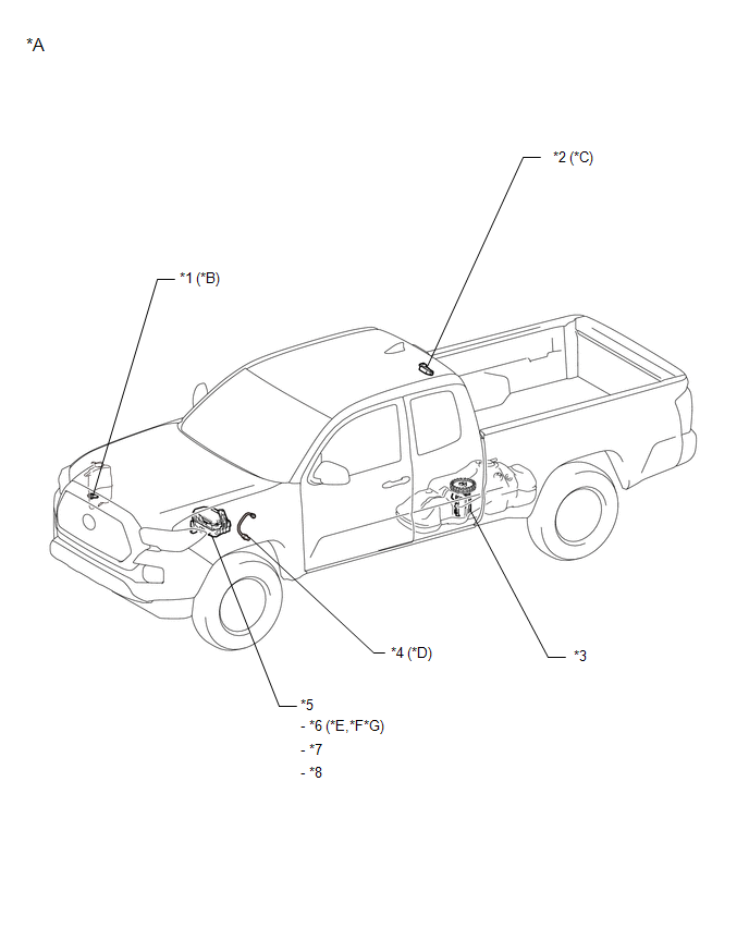
ILLUSTRATION
|
*A |
for Access Cab |
*B |
w/ Washer Fluid Level Warning |
|
*C |
w/ Tire Pressure Warning System |
*D |
for Manual Transmission |
|
*E |
for Hydraulic Booster Type |
*F |
for Vacuum Booster Type |
|
*G |
w/ Trailer Towing System |
- |
- |
|
*1 |
LEVEL WARNING SWITCH ASSEMBLY |
*2 |
DOOR CONTROL AND TIRE PRESSURE MONITORING SYSTEM RECEIVER ASSEMBLY |
|
*3 |
FUEL SUCTION WITH PUMP AND GAUGE TUBE ASSEMBLY - FUEL SENDER GAUGE ASSEMBLY |
*4 |
BACK-UP LIGHT SWITCH ASSEMBLY |
|
*5 |
ENGINE ROOM RELAY BLOCK |
*6 |
STOP RELAY |
|
*7 |
TOWING FUSE |
*8 |
ECU-B NO. 3 FUSE |
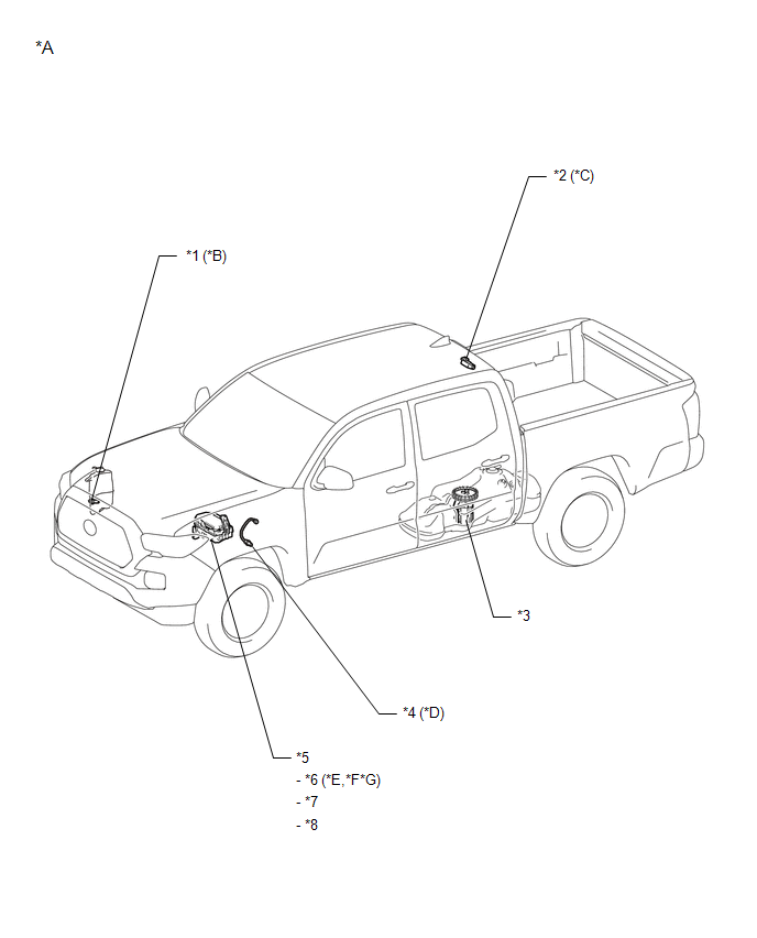
ILLUSTRATION
|
*A |
for Double Cab |
*B |
w/ Washer Fluid Level Warning |
|
*C |
w/ Tire Pressure Warning System |
*D |
for Manual Transmission |
|
*E |
for Hydraulic Booster Type |
*F |
for Vacuum Booster Type |
|
*G |
w/ Trailer Towing System |
- |
- |
|
*1 |
LEVEL WARNING SWITCH ASSEMBLY |
*2 |
DOOR CONTROL AND TIRE PRESSURE MONITORING SYSTEM RECEIVER ASSEMBLY |
|
*3 |
FUEL SUCTION WITH PUMP AND GAUGE TUBE ASSEMBLY - FUEL SENDER GAUGE ASSEMBLY |
*4 |
BACK-UP LIGHT SWITCH ASSEMBLY |
|
*5 |
ENGINE ROOM RELAY BLOCK |
*6 |
STOP RELAY |
|
*7 |
TOWING FUSE |
*8 |
ECU-B NO. 3 FUSE |
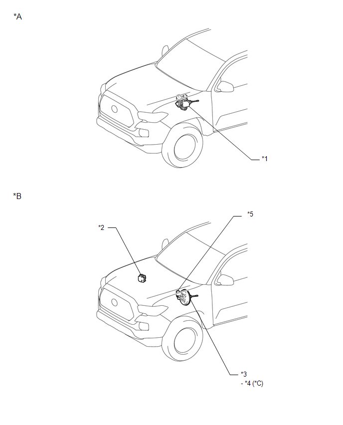
ILLUSTRATION
|
*A |
for Hydraulic Booster Type |
*B |
for Vacuum Booster Type |
|
*C |
for 2GR-FKS |
- |
- |
|
*1 |
BRAKE BOOSTER WITH MASTER CYLINDER ASSEMBLY - SKID CONTROL ECU |
*2 |
BRAKE ACTUATOR ASSEMBLY - SKID CONTROL ECU |
|
*3 |
BRAKE BOOSTER ASSEMBLY |
*4 |
VACUUM WARNING SWITCH ASSEMBLY |
|
*5 |
BRAKE MASTER CYLINDER RESERVOIR SUB-ASSEMBLY - BRAKE FLUID LEVEL WARNING SWITCH |
- |
- |
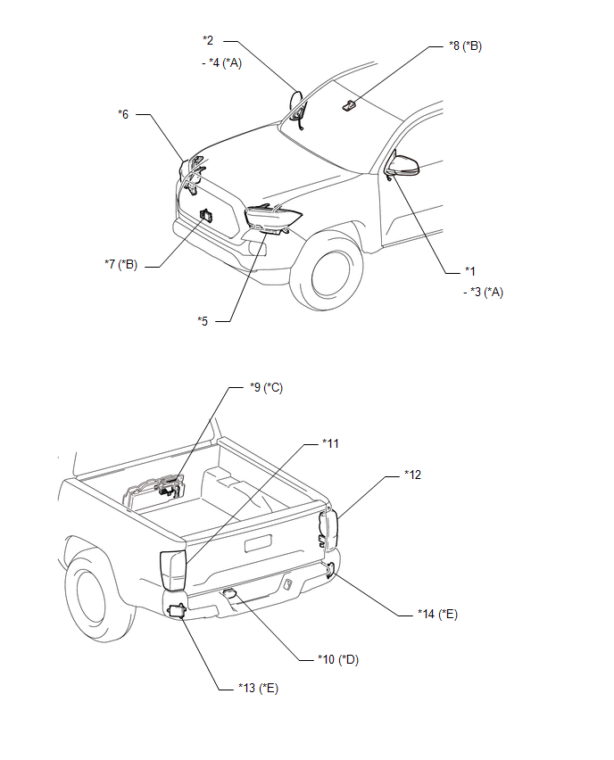
ILLUSTRATION
|
*A |
for Outer Rear View Mirror Type Side Turn Signal Light |
*B |
w/ Toyota Safety Sense P |
|
*C |
w/ Stereo Component Amplifier |
*D |
w/ Trailer Towing System |
|
*E |
w/ Blind Spot Monitor System |
- |
- |
|
*1 |
OUTER REAR VIEW MIRROR ASSEMBLY LH |
*2 |
OUTER REAR VIEW MIRROR ASSEMBLY RH |
|
*3 |
SIDE TURN SIGNAL LIGHT ASSEMBLY LH |
*4 |
SIDE TURN SIGNAL LIGHT ASSEMBLY RH |
|
*5 |
HEADLIGHT ASSEMBLY LH |
*6 |
HEADLIGHT ASSEMBLY RH |
|
*7 |
MILLIMETER WAVE RADAR SENSOR ASSEMBLY |
*8 |
FORWARD RECOGNITION CAMERA |
|
*9 |
STEREO COMPONENT AMPLIFIER ASSEMBLY |
*10 |
TRAILER SOCKET |
|
*11 |
REAR COMBINATION LIGHT ASSEMBLY LH |
*12 |
REAR COMBINATION LIGHT ASSEMBLY RH |
|
*13 |
BLIND SPOT MONITOR SENSOR LH |
*14 |
BLIND SPOT MONITOR SENSOR RH |
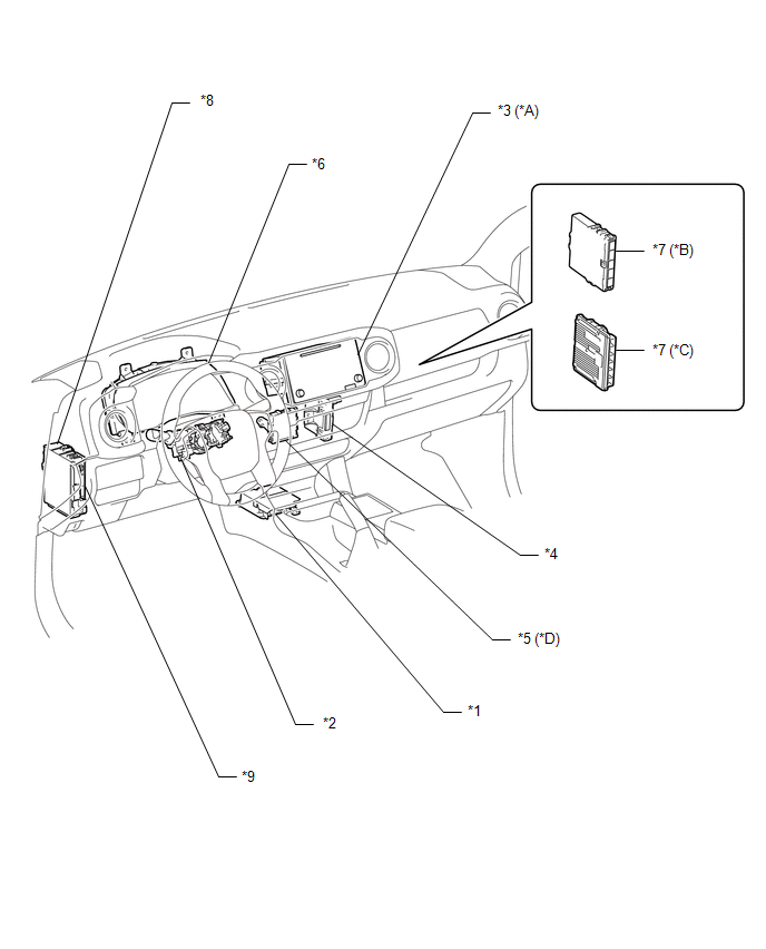
ILLUSTRATION
|
*A |
for Navigation Receiver Type |
*B |
for 2TR-FE |
|
*C |
for 2GR-FKS |
*D |
w/ Intuitive Parking Assist System |
|
*1 |
AIRBAG SENSOR ASSEMBLY |
*2 |
HEADLIGHT DIMMER SWITCH ASSEMBLY |
|
*3 |
NAVIGATION RECEIVER ASSEMBLY |
*4 |
AIR CONDITIONING AMPLIFIER ASSEMBLY |
|
*5 |
CLEARANCE WARNING ECU ASSEMBLY |
*6 |
COMBINATION METER ASSEMBLY |
|
*7 |
ECM |
*8 |
DRIVER SIDE JUNCTION BLOCK - METER FUSE |
|
*9 |
MAIN BODY ECU (MULTIPLEX NETWORK BODY ECU) |
- |
- |
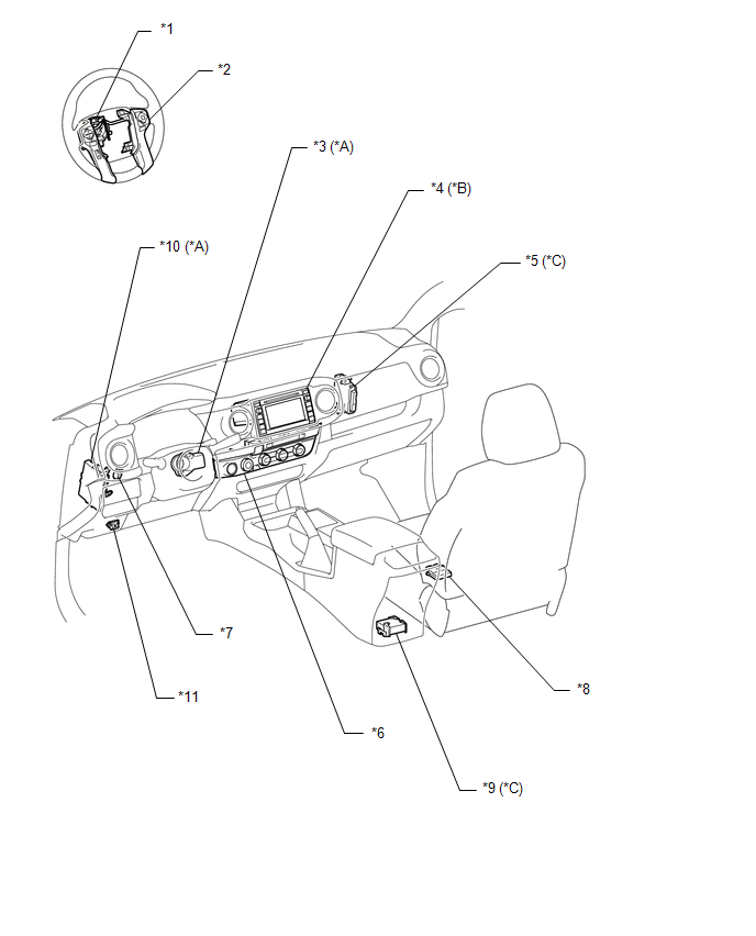
ILLUSTRATION
|
*A |
w/ Smart Key System |
*B |
for Radio and Display Type |
|
*C |
for 4WD |
*D |
w/ Voltage Inverter |
|
*1 |
SPIRAL CABLE WITH SENSOR SUB-ASSEMBLY |
*2 |
STEERING PAD SWITCH ASSEMBLY |
|
*3 |
STEERING LOCK ACTUATOR OR UPR BRACKET ASSEMBLY (STEERING LOCK ECU) |
*4 |
RADIO AND DISPLAY RECEIVER ASSEMBLY |
|
*5 |
4WD CONTROL ECU ASSEMBLY |
*6 |
AIR CONDITIONING CONTROL ASSEMBLY - HAZARD WARNING SIGNAL SWITCH ASSEMBLY |
|
*7 |
STOP LIGHT SWITCH ASSEMBLY |
*8 |
OCCUPANT CLASSIFICATION ECU |
|
*9 |
VOLTAGE INVERTER ASSEMBLY |
*10 |
CERTIFICATION ECU (SMART KEY ECU ASSEMBLY) |
|
*11 |
DLC3 |
- |
- |
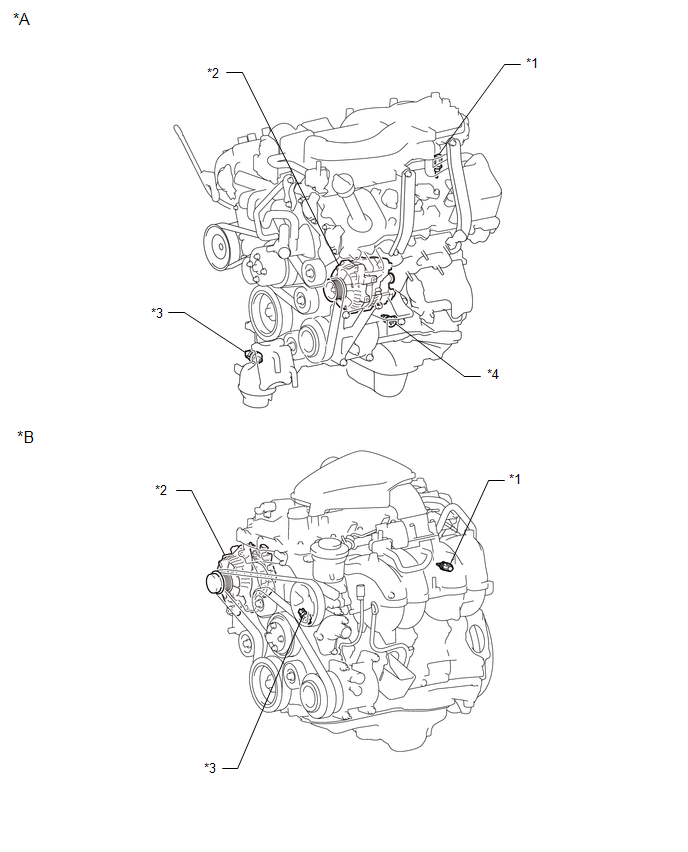
ILLUSTRATION
|
*A |
for 2GR-FKS |
*B |
for 2TR-FE |
|
*1 |
ENGINE COOLANT TEMPERATURE SENSOR |
*2 |
GENERATOR ASSEMBLY |
|
*3 |
ENGINE OIL PRESSURE SWITCH ASSEMBLY |
*4 |
ENGINE OIL LEVEL SENSOR |

 Precaution
PRECAUTION
1. IGNITION SWITCH EXPRESSIONS
(a) The type of ignition switch used on this model differs according to the specifications
of the vehicle. The expressions listed in the table below are u ...
Other materials:
Inspection
INSPECTION
PROCEDURE
1. INSPECT REAR AXLE SHAFT
(a) Using a dial indicator, measure the runout of the shaft and flange.
Maximum runout:
Shaft runout: 1.5 mm (0.0591 in.)
Flange runout: 0.05 mm (0.0020 in.)
If the rear axle shaft or flange is damaged or worn, or the runout is greater
than ...
Connecting Bluetooth®
The following can be performed using Bluetooth┬« wireless communication: ■
A portable audio player can be operated and listened to via multimedia system
■ Hands-free phone calls can be made via a cellular phone
In order to use wireless communication, register and connect a Bluetooth┬ ...
Voice Recognition Microphone Disconnected (B1579)
DESCRIPTION
The navigation receiver assembly and telephone microphone assembly are connected
to each other using the microphone connection detection signal lines.
This DTC is stored when the microphone connection detection signal is disconnected.
DTC Code
DTC Detection Con ...
