Toyota Tacoma (2015-2018) Service Manual: Power Outlet Socket(for Front Side)
Components
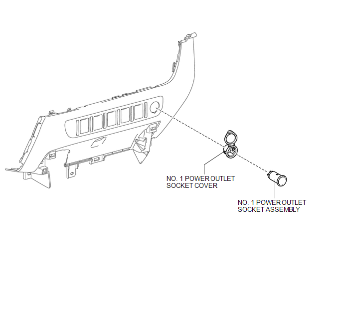
COMPONENTS
ILLUSTRATION
Removal
REMOVAL
PROCEDURE
1. REMOVE INSTRUMENT PANEL LOWER CENTER FINISH PANEL
(See page .gif) )
)
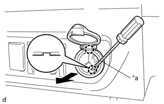
2. REMOVE NO. 1 POWER OUTLET SOCKET ASSEMBLY
|
(a) Using a screwdriver with its tip wrapped in protective tape, disengage the 2 claws to remove the No. 1 power outlet socket assembly as shown in the illustration. Text in Illustration
|
|
3. REMOVE NO. 1 POWER OUTLET SOCKET COVER
|
(a) Disengage the 2 claws to remove the No. 1 power outlet socket cover. |
|
Installation
INSTALLATION
PROCEDURE
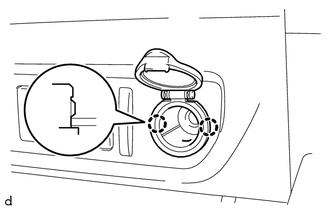
1. INSTALL NO. 1 POWER OUTLET SOCKET COVER
(a) Engage the 2 claws to install the No. 1 power outlet socket cover.
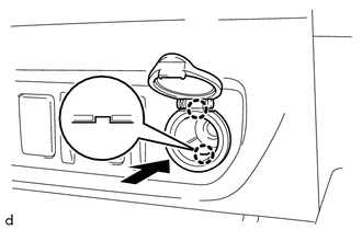
2. INSTALL NO. 1 POWER OUTLET SOCKET ASSEMBLY
|
(a) Engage the 2 claws to install the No. 1 power outlet socket assembly as shown in the illustration. |
|
3. INSTALL INSTRUMENT PANEL LOWER CENTER FINISH PANEL
(See page .gif) )
)
 Inverter Relay
On-vehicle Inspection
ON-VEHICLE INSPECTION
PROCEDURE
1. INSPECT INVERTER RELAY
(a) Check the resistance.
(1) Measure the resistance according to the value(s) in the table below.
...
 Power Outlet Socket(for Rear Side)
Components
COMPONENTS
ILLUSTRATION
*1
USB CHARGER SOCKET
-
-
Removal
REMOVAL
PROCEDURE
1. REMOVE REAR CONSOLE BOX ASSEMBLY
Click here ...
Other materials:
Dtc Check / Clear
DTC CHECK / CLEAR
1. CHECK DTC
(a) Connect the Techstream to the DLC3.
(b) Turn the ignition switch to ON.
(c) Turn the back sonar or clearance sonar switch assembly on.
(d) Turn the Techstream on.
(e) Enter the following menus: Body Electrical / Intuitive P/A / Trouble Codes.
(f) Check for D ...
HD Radio Tuner Malfunction (B1551,B15A0,B15AD,B15B0,B15B3,B15B4,B15B7)
DESCRIPTION
These DTCs are stored when a malfunction occurs in the navigation receiver assembly.
DTC No.
DTC Detection Condition
Trouble Area
B1551
When one of the conditions below is met:
"HD Radio" tuner decoder ...
TRAC OFF Indicator Light does not Come ON
DESCRIPTION
Refer to TRAC OFF Indicator Light Remains ON (See page
).
WIRING DIAGRAM
Refer to TRAC OFF Indicator Light Remains ON (See page
).
CAUTION / NOTICE / HINT
NOTICE:
When replacing the skid control ECU (master cylinder solenoid), perform
calibration (See page
).
...
