Toyota Tacoma (2015-2018) Service Manual: Personal Light Assembly
Components
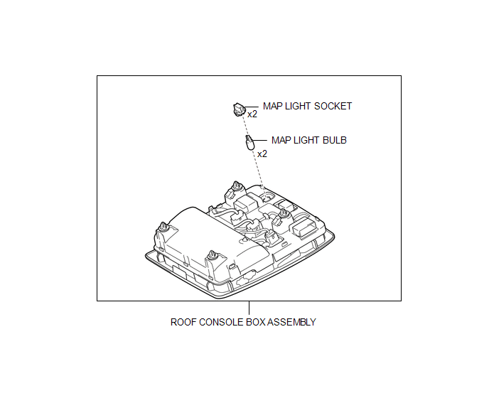
COMPONENTS
ILLUSTRATION
Installation
INSTALLATION
PROCEDURE
1. INSTALL MAP LIGHT BULB
(a) Install the 2 map light bulbs to the 2 map light sockets.
|
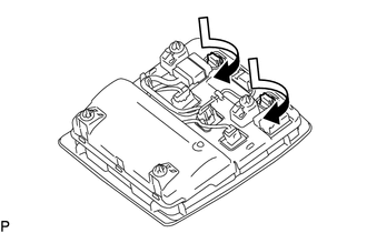
(b) Turn the 2 map light sockets with 2 map light bulbs in the direction indicated by the arrow shown in the illustration to install them |
|
2. INSTALL ROOF CONSOLE BOX ASSEMBLY
(a) Connect the connector.
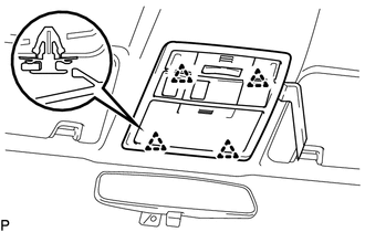
(b) Engage the 4 clips to install the roof console box assembly.
Removal
REMOVAL
PROCEDURE
1. REMOVE ROOF CONSOLE BOX ASSEMBLY
|
(a) Using a moulding remover D, disengage the 4 clips to separate the roof console box assembly. |
|
(b) Disconnect the connector to remove the roof console box assembly.
2. REMOVE MAP LIGHT BULB
|
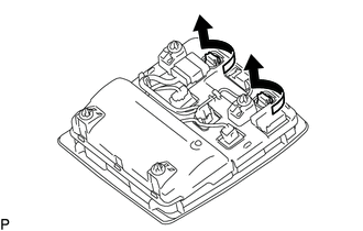
(a) Turn the 2 map light sockets with the 2 map light bulbs in the direction indicated by the arrow shown in the illustration to remove them. |
|
(b) Remove the map light bulb from the map light socket.
 Low Beam Headlight Circuit
DESCRIPTION
The main body ECU (multiplex network body ECU) controls the low beam headlights.
WIRING DIAGRAM
CAUTION / NOTICE / HINT
NOTICE:
Inspect the fuses for circuits related to thi ...
 Rear Combination Light Assembly
Components
COMPONENTS
ILLUSTRATION
Disassembly
DISASSEMBLY
CAUTION / NOTICE / HINT
HINT:
Use the same procedure for both the LH and RH sides.
The procedure described below is ...
Other materials:
Diagnosis System
DIAGNOSIS SYSTEM
1. DESCRIPTION
The ECM stores DTCs (Diagnostic Trouble Codes) when trouble occurs on the vehicle.
The diagnosis system allows reading of DTCs stored in the ECM when a the Techstream
is connected to the DLC3 (Data Link Connector 3). If the CRUISE MAIN indicator light
does not ...
Lost Communication with Vehicle Dynamics Control Module Missing Message (U012287)
DESCRIPTION
The ECM receives signals from the skid control ECU (brake actuator assembly)
via CAN communication.
DTC No.
DTC Detection Condition
Trouble Area
MIL
Note
U012287
While cruise control main switch ON, co ...
Components
COMPONENTS
ILLUSTRATION
ILLUSTRATION
ILLUSTRATION
ILLUSTRATION
ILLUSTRATION
ILLUSTRATION
ILLUSTRATION
ILLUSTRATION
...
