Toyota Tacoma (2015-2018) Service Manual: Automatic Transmission Unit(for 2gr-fks)
Components
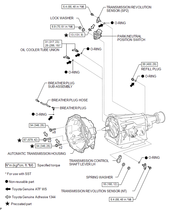
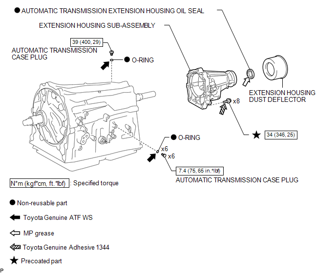
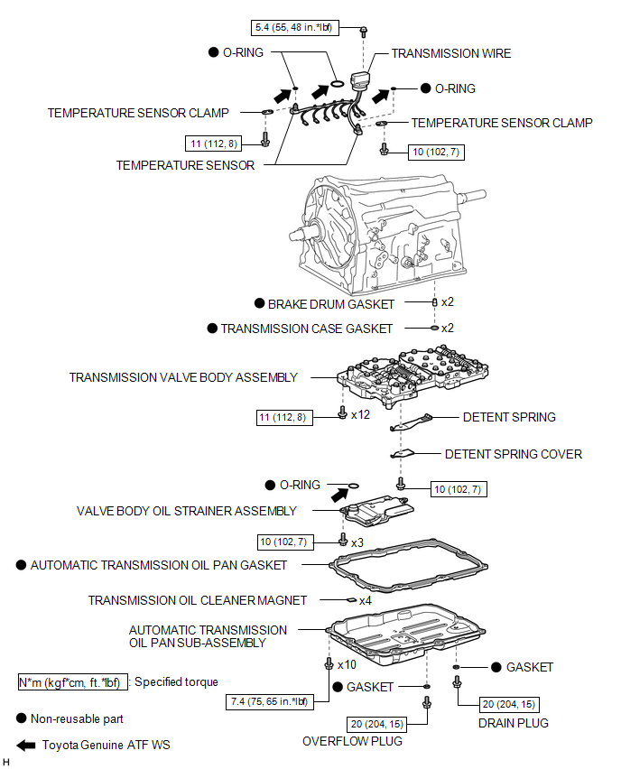
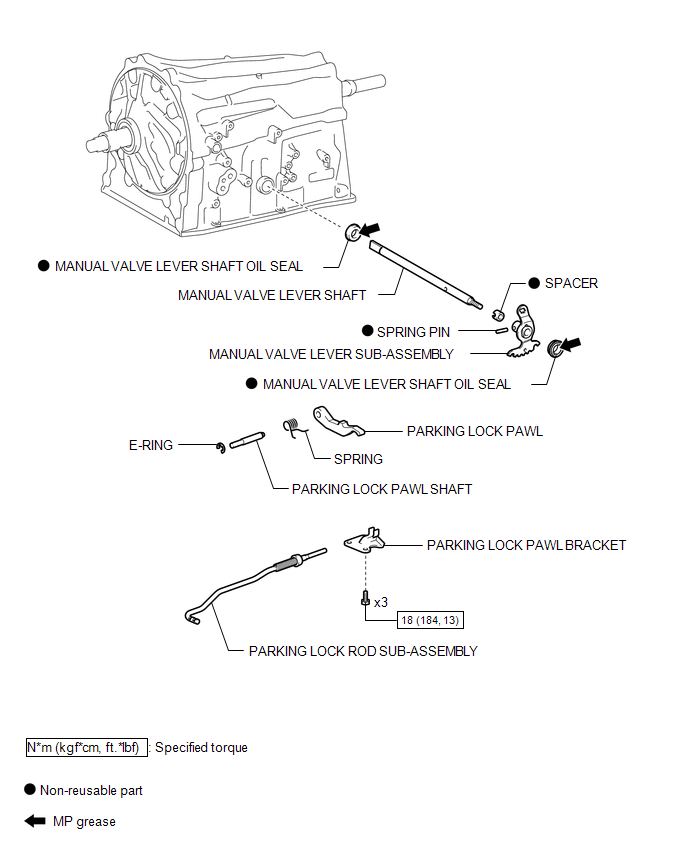
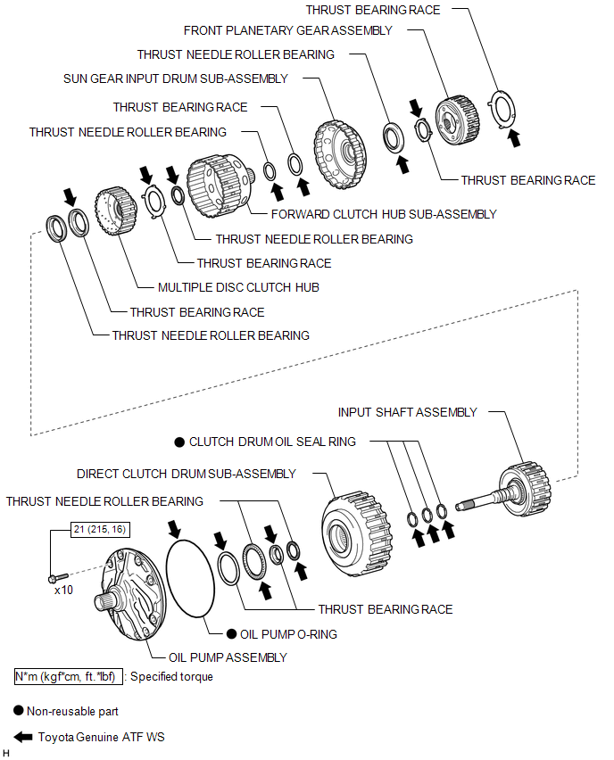
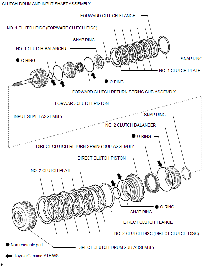
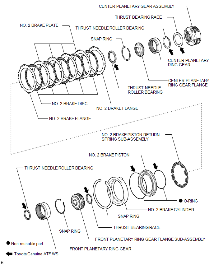
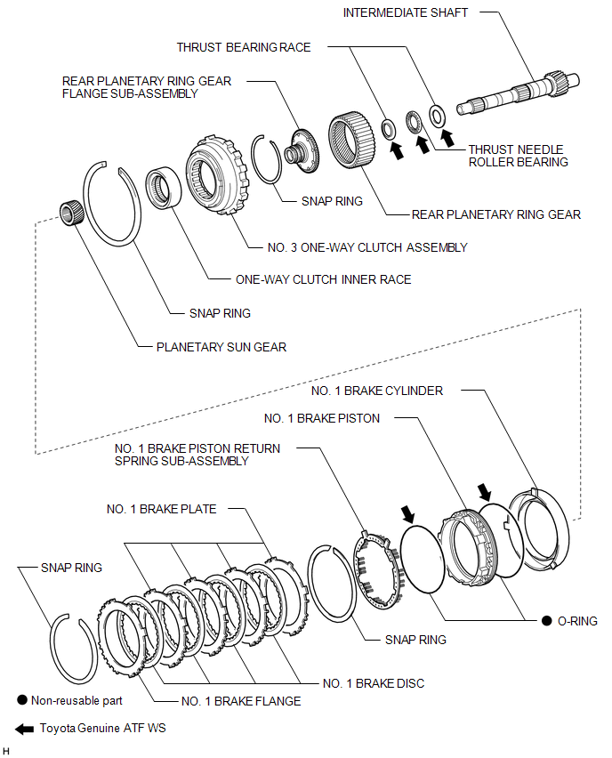
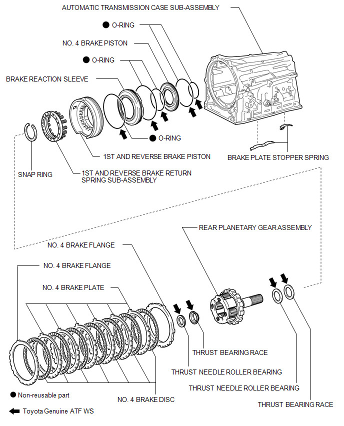
COMPONENTS
ILLUSTRATION
ILLUSTRATION
ILLUSTRATION
ILLUSTRATION
ILLUSTRATION
ILLUSTRATION
ILLUSTRATION
ILLUSTRATION
ILLUSTRATION
 Pattern Select Switch
Components
COMPONENTS
ILLUSTRATION
Removal
REMOVAL
PROCEDURE
1. REMOVE INSTRUMENT PANEL LOWER CENTER FINISH PANEL
(See page )
2. REMOVE PATTERN SELECT SWITCH ASSEMBLY
(a) D ...
 Automatic Transmission Unit(for 2tr-fe)
Components
COMPONENTS
ILLUSTRATION
ILLUSTRATION
ILLUSTRATION
ILLUSTRATION
ILLUSTRATION
ILLUSTRATION
ILLUSTRATION
ILLUSTRATION
ILLUSTRATION
...
Other materials:
Front Radar Sensor Region Code Mismatch (C1A0A)
DESCRIPTION
When the destination information in the millimeter wave radar sensor assembly
and forward recognition camera do not match, DTC C1A0A is stored.
DTC No.
Detection Item
DTC Detection Condition
Trouble Area
MIL
C1A0 ...
Precaution
PRECAUTION
1. IGNITION SWITCH EXPRESSIONS
(a) The type of ignition switch used on this model differs according to the specifications
of the vehicle. The expressions listed in the table below are used in this section.
Expression
Ignition Switch (Position)
Engine ...
Diagnosis System
DIAGNOSIS SYSTEM
1. DESCRIPTION
The 4 wheel drive control ECU records DTCs when the ECU detects a malfunction
in the ECU itself or in system circuits.
The DTCs can be read through the DLC3 of the vehicle. When the system seems to
be malfunctioning, use the Techstream to check for malfunctions ...
