Toyota Tacoma (2015-2018) Service Manual: Parts Location
PARTS LOCATION
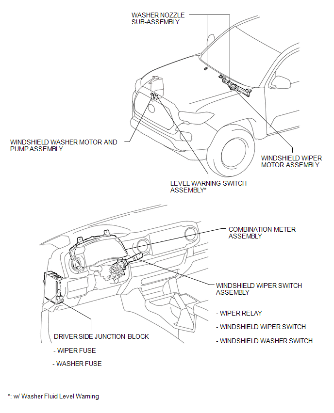
ILLUSTRATION

 Precaution
PRECAUTION
1. IGNITION SWITCH EXPRESSIONS
(a) The type of ignition switch used on this model differs depending on the specifications
of the vehicle. The expressions listed in the table below are u ...
Other materials:
Cargo Light
Components
COMPONENTS
ILLUSTRATION
Removal
REMOVAL
PROCEDURE
1. REMOVE ROOF HEADLINING ASSEMBLY
for Double Cab:
(See page
)
for Access Cab:
(See page
)
2. REMOVE CARGO LIGHT ASSEMBLY (CENTER STOP LIGHT ASSEMBLY)
(a) Remove the 2 nuts.
...
ABS Control System Malfunction (43)
DESCRIPTION
This DTC is output when the VSC system detects a malfunction in the ABS system.
When DTC 43 is stored, there is no malfunction in the skid control ECU (master cylinder
solenoid).
DTC No.
DTC Detecting Condition
Trouble Areas
43
...
Open in One Side of Bus 2 Branch Line
DESCRIPTION
When the CAN bus main lines are normal (no open, short to ground, short to +B
or short between lines) and there is an ECU or sensor on the "Communication Bus
Check" screen that is indicated as not communicating or whose connection status
on the "Communication Bus Ch ...
