Toyota Tacoma (2015-2018) Service Manual: Operation Check
OPERATION CHECK
1. MALFUNCTION DISPLAY (MULTI-INFORMATION DISPLAY)
(a) Open circuit indication
(1) If there is an open circuit between a No. 1 ultrasonic sensor and the clearance warning ECU assembly or a sensor is malfunctioning, the malfunction is displayed as shown in the illustration.
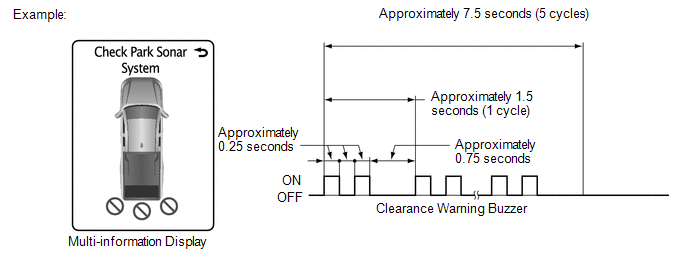
HINT:
If a sensor has an open circuit, check for DTCs and troubleshoot according to
each inspection procedure (See page .gif) ).
).
(b) Frozen indication
(1) If a sensor is covered with foreign matter, such as mud or snow, the affected sensor is displayed as shown in the illustration.
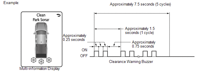
HINT:
- If a frozen indication is displayed, read Precaution for Intuitive Parking
Assist System first and confirm that the sensor is not covered with foreign
matter (See page ).
- Check for DTCs and troubleshoot according to each inspection procedure
after confirming that the sensor is not covered with foreign matter (See
page ).
2. DETECTION RANGE MEASUREMENT AND DISPLAY INSPECTION
NOTICE:
The following measurement and inspection will be performed with the shift lever in a position other than P. Be sure to apply the parking lever and depress the brake pedal firmly to prevent the vehicle from moving.
(a) Turn the ignition switch to ON.
(b) Turn the back sonar or clearance sonar switch assembly on.
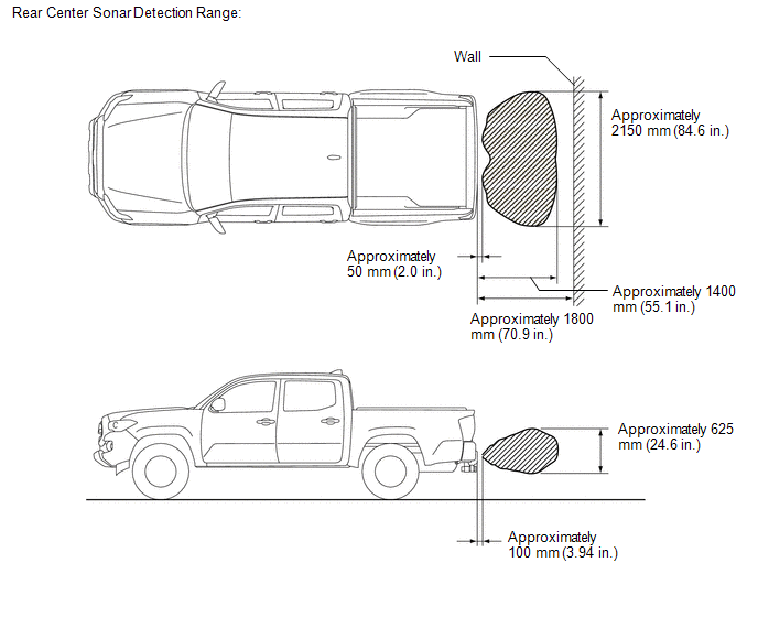
(c) Detection range measurement:
(1) Move the shift lever according to the table below.
|
Measurement Area |
Shift Lever Position |
|---|---|
|
Rear Corner |
R |
|
Rear Center |
(2) Move a 60 mm (2.36 in.) diameter pole near each sensor to measure its detection range. When measuring the longest-range detection of the front center sonar and the rear center sonar, use a wall or equivalent.
NOTICE:
These detection ranges are applicable when positioning the 60 mm (2.36 in.) diameter pole parallel or perpendicular to the ground. The detection range varies depending on the measuring method and type of obstacle (such as walls).
HINT:
Have an assistant move the pole.
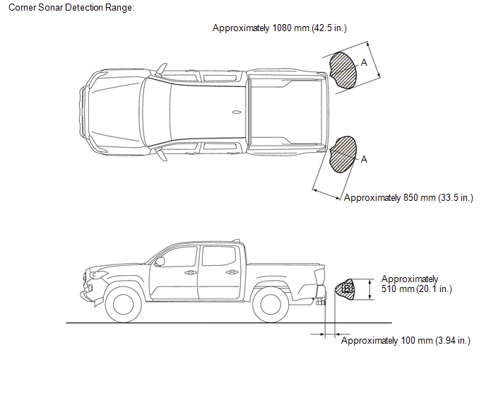
NOTICE:
The No. 1 ultrasonic sensor side view detection range (hatched area labeled (B)) represents the cross section of the top view detection range (A). The hatched area (B) does not represent the entire side view detection range.
(d) Rear corner sonar display and buzzer operation check
(1) When the No. 1 ultrasonic sensors (rear corner sonar) have detected an obstacle, check the display and check that the buzzer sounds.
Operation Condition|
Ignition Switch |
Back Sonar or Clearance Sonar Switch Assembly |
Shift Lever Position |
Vehicle Speed |
|---|---|---|---|
|
ON |
On |
R |
- |
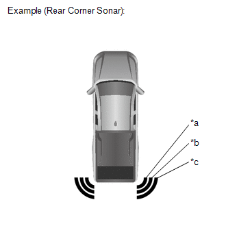 Text in Illustration
|
*a |
Close-range Detection |
|
*b |
Medium-range Detection |
|
*e |
Long-range Detection |
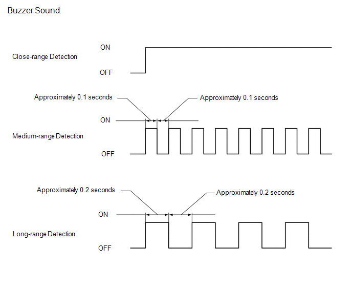
Standard:
Multi-information Display and Buzzer|
Detection Range |
During Judgment |
Obstacle |
|---|---|---|
|
Close-range detection Within approximately 400 +/- 40 mm (15.7 +/- 1.57 in.) |
Buzzer: Sounds continuously Number of bars displayed: 1 (blinking) |
60 mm (2.36 in.) diameter pole |
|
Medium-range detection From approximately 400 +/- 40 to 600 +/- 60 mm (15.7 +/- 1.57 to 23.6 +/- 2.36 in.) |
Buzzer: Sounds intermittently (ON: 0.075 seconds / OFF: 0.075 seconds) Number of bars displayed: 2 (illuminated) |
60 mm (2.36 in.) diameter pole |
|
Long-range detection From approximately 600 +/- 60 to 850 +/- 90 mm (23.6 +/- 2.36 to 33.5 +/- 3.54 in.) |
Buzzer: Sounds intermittently (ON: 0.15 seconds / OFF: 0.15 seconds) Number of bars displayed: 3 (illuminated) |
60 mm (2.36 in.) diameter pole |
HINT:
Ultrasonic waves are used to measure the detection range; however, the detection range may vary depending on the ambient temperature.
(e) Rear center sonar display and buzzer operation check
(1) When the No. 1 ultrasonic sensors (rear center sonar) have detected an obstacle, check the display and check that the buzzer sounds.
Operation Condition|
Ignition Switch |
Back Sonar or Clearance Sonar Switch Assembly |
Shift Lever Position |
Vehicle Speed |
|---|---|---|---|
|
ON |
On |
R |
- |
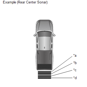 Text in Illustration
|
*a |
Close-range Detection |
|
*b |
Medium-range Detection |
|
*c |
Long-range Detection |
|
*d |
Longest-range Detection |
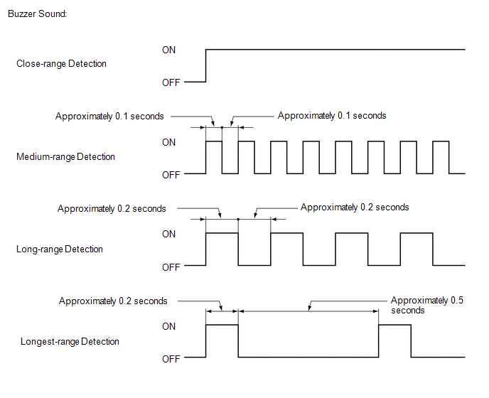
Standard:
Multi-information Display and Buzzer|
Detection Range |
During Detection |
Obstacle |
|---|---|---|
|
Close-range detection Within approximately 500 +/- 50 mm (19.7 +/- 1.97 in.) |
Buzzer: Sounds continuously Number of bars displayed: 1 (blinking) |
60 mm (2.36 in.) diameter pole |
|
Medium-range detection From approximately 500 +/- 50 to 750 +/- 80 mm (19.7 +/- 1.97 to 29.5 +/- 3.15 in.) |
Buzzer: Sounds intermittently (ON: 0.1 seconds / OFF: 0.1 seconds) Number of bars displayed: 2 (illuminated) |
60 mm (2.36 in.) diameter pole |
|
Long-range detection From approximately 750 +/- 80 to 1000 +/- 100 mm (29.5 +/- 3.15 to 39.4 +/- 3.94 in.) |
Buzzer: Sounds intermittently (ON: 0.2 seconds / OFF: 0.2 seconds) Number of bars displayed: 3 (illuminated) |
60 mm (2.36 in.) diameter pole |
|
Longest-range detection From approximately 1400 +/- 140 to 1800 +/- 180 mm (39.4 +/- 3.94 to 70.9 +/- 7.09 in.) |
Buzzer: Sounds intermittently (ON: 0.2 seconds / OFF: 0.5 seconds) Number of bars displayed: 4 (illuminated) |
Wall |
HINT:
Ultrasonic waves are used to measure the detection range; however, the detection range may vary depending on the ambient temperature.
 System Description
SYSTEM DESCRIPTION
1. GENERAL
(a) This system uses ultrasonic sensors to detect any obstacles at the corners
and the rear of the vehicle. The system then informs the driver of the distance
betwe ...
 Customize Parameters
CUSTOMIZE PARAMETERS
PROCEDURE
1. CUSTOMIZE INTUITIVE PARKING ASSIST SYSTEM
(a) Customizing with the Techstream
NOTICE:
When the customer requests a change in a function, first make sure ...
Other materials:
Brake Fluid(for Hydraulic Brake Booster)
On-vehicle Inspection
ON-VEHICLE INSPECTION
PROCEDURE
1. INSPECT FLUID LEVEL IN RESERVOIR
(a) Turn the ignition switch to OFF, and depress the brake pedal more
than 40 times (until the pedal reaction feels light and pedal stroke becomes
longer), and adjust the fluid level to ...
Steering Angle Sensor Power Source Voltage Malfunction (C1432)
DESCRIPTION
Steering angle sensor (spiral cable with sensor sub-assembly) signals are sent
to the skid control ECU (master cylinder solenoid) via the CAN communication system.
When there is a malfunction in the CAN communication system, it is detected by the
steering angle sensor zero point m ...
Installation
INSTALLATION
PROCEDURE
1. INSTALL OIL COOLER TUBE
(a) Install the oil cooler tube to the vehicle body with the 2 bolts.
Torque:
28 N·m {286 kgf·cm, 21 ft·lbf}
2. INSTALL NO. 4 OIL COOLER INLET HOSE AND NO. 4 OIL COOLER OUTLET HOSE
NOTICE:
When connecting the hoses to the tube, su ...
