Toyota Tacoma (2015-2018) Service Manual: Parts Location
PARTS LOCATION
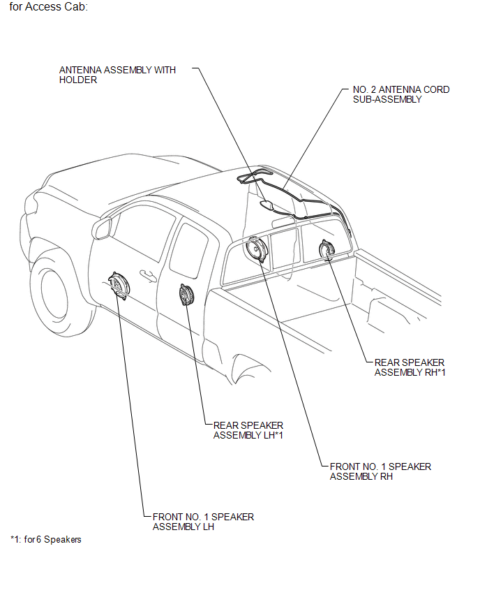
ILLUSTRATION

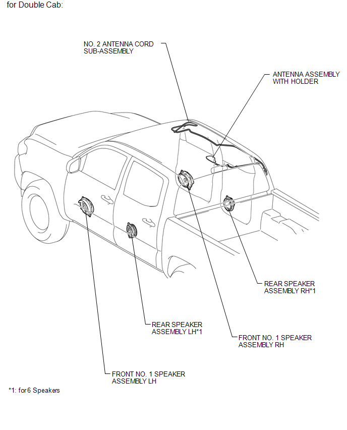
ILLUSTRATION
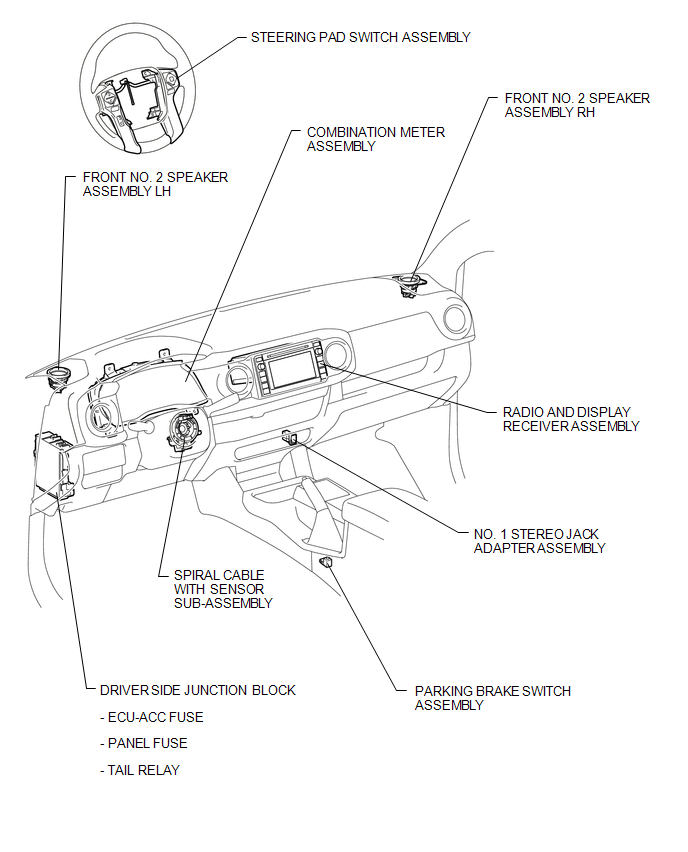
ILLUSTRATION
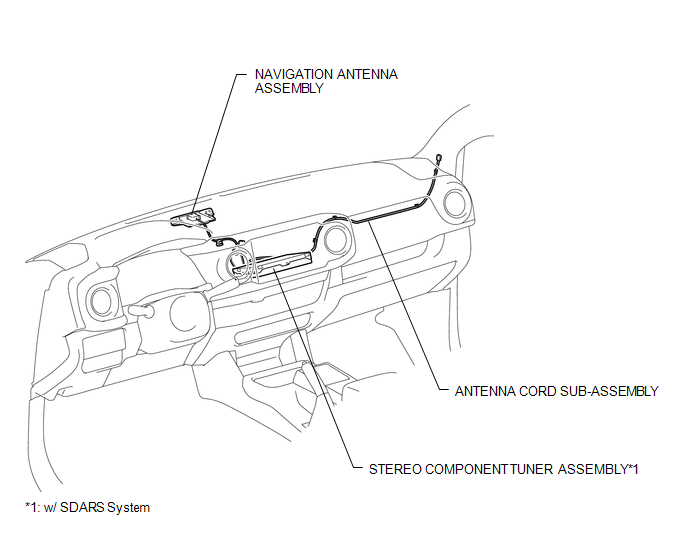
ILLUSTRATION
ILLUSTRATION
 Precaution
PRECAUTION
1. IGNITION SWITCH EXPRESSIONS
(a) The type of ignition switch used on this model differs according to the specifications
of the vehicle. The expressions listed in the table below are u ...
 System Diagram
SYSTEM DIAGRAM
...
Other materials:
Operation Check
OPERATION CHECK
1. INSPECT INTERIOR LIGHT CONTROL OPERATION
NOTICE:
Perform this inspection with the customize parameters at the default settings.
The interior light control illuminates the lights below.
Engine Switch Illumination*1
Transponder Key Coil (Ignition Key Cylinder Light)* ...
IG Power Source Circuit
DESCRIPTION
The main power source is supplied to the air conditioning amplifier assembly
when the ignition switch is turned to ON.
The power is used for operating the air conditioning amplifier assembly, servo
motors, etc.
WIRING DIAGRAM
CAUTION / NOTICE / HINT
NOTICE:
Inspect the fuses ...
Replacement
REPLACEMENT
CAUTION / NOTICE / HINT
CAUTION:
Prolonged and repeated contact with engine oil will result in the removal
of natural oils from the skin, leading to dryness, irritation and dermatitis.
In addition, used engine oil contains potentially harmful contaminants which
may ...
