Toyota Tacoma (2015-2018) Service Manual: System Diagram
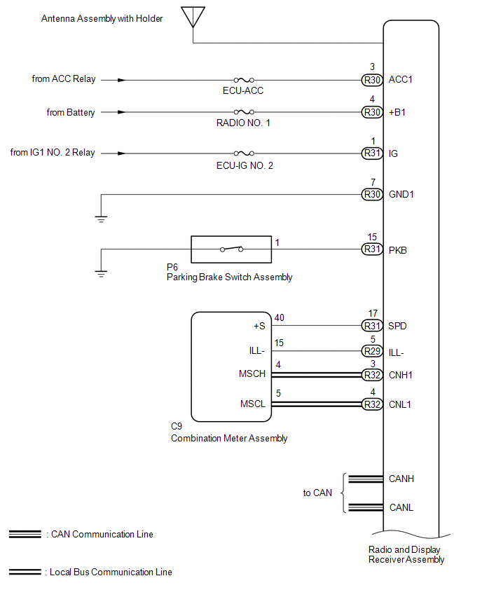
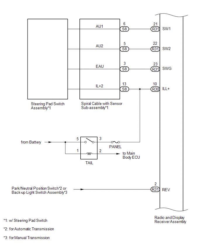
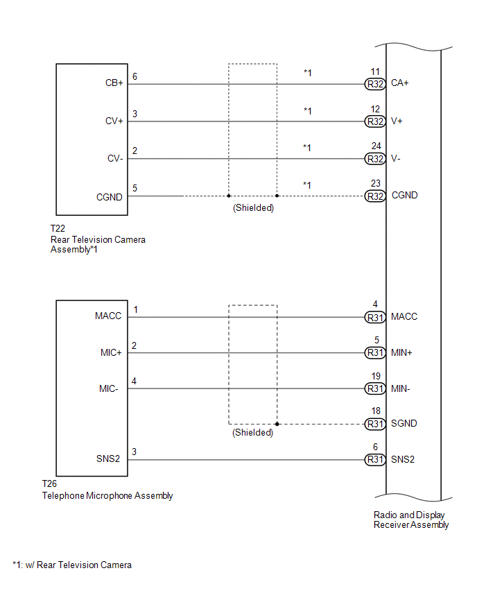
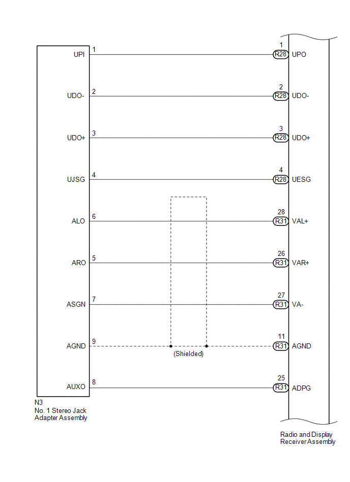
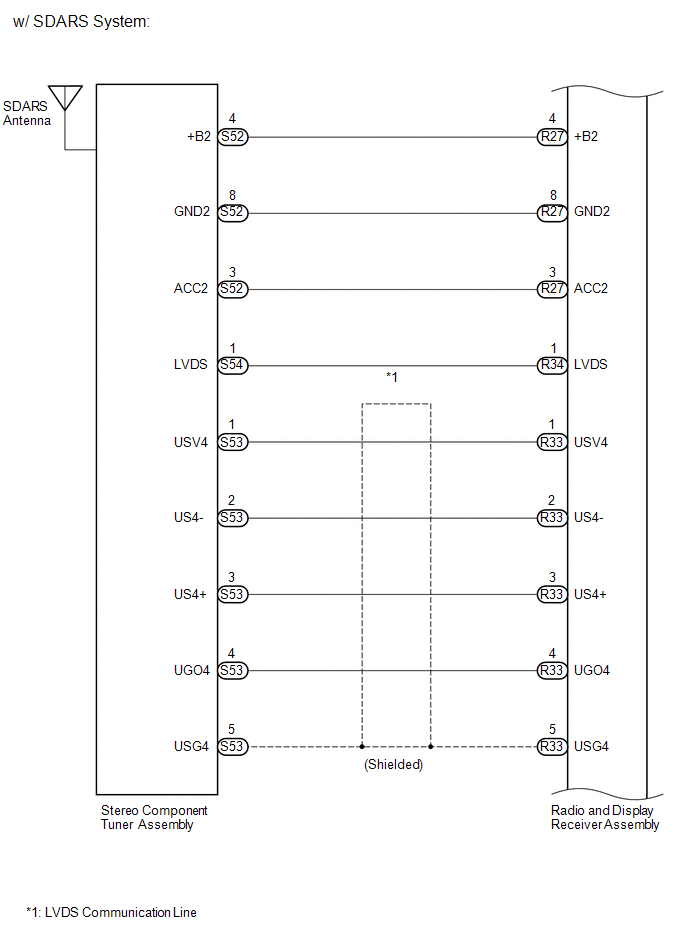
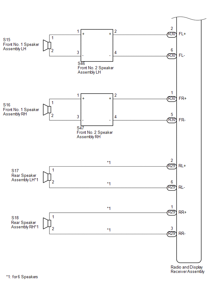
SYSTEM DIAGRAM
 Parts Location
PARTS LOCATION
ILLUSTRATION
ILLUSTRATION
ILLUSTRATION
ILLUSTRATION
ILLUSTRATION
...
 System Description
SYSTEM DESCRIPTION
1. TOUCH SWITCH OUTLINE
Touch switches are touch-sensitive (interactive) switches operated by touching
the screen. When a switch is pressed, the outer film bends in to contact t ...
Other materials:
Control Module Communication Bus OFF (U0073,U0100,U0114,U0123,U0124,U0126)
DESCRIPTION
The skid control ECU (master cylinder solenoid) receives the signals from the
ECM, steering angle sensor (spiral cable with sensor sub-assembly), 4 wheel drive
control ECU*, and yaw rate and acceleration sensor (airbag sensor assembly) via
the CAN communication system.
*: ...
TRAC OFF Indicator Light Remains ON
DESCRIPTION
In 2WD mode:
Operation of the VSC OFF switch changes the vehicle between normal mode,
TRAC OFF mode (AUTO LSD mode) and VSC OFF mode. During normal mode, pressing
the VSC OFF switch for a short amount of time changes the vehicle to TRAC
OFF mode (AUTO LSD mode), TR ...
Motor Malfunction (C1427)
DESCRIPTION
DTC No.
Detection Item
DTC Detection Condition
Trouble Area
C1427
Motor Malfunction
Actuator pump motor does not operate properly.
Brake actuator assembly (Ground circuit)
Brak ...
