Toyota Tacoma (2015-2018) Service Manual: Parts Location
PARTS LOCATION
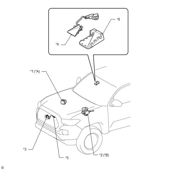
ILLUSTRATION
|
*A |
for Vacuum Brake Booster |
*B |
for Hydraulic Brake Booster |
|
*1 |
SKID CONTROL ECU (BRAKE ACTUATOR ASSEMBLY) |
*2 |
SKID CONTROL ECU (MASTER CYLINDER SOLENOID) |
|
*3 |
MILLIMETER WAVE RADAR SENSOR ASSEMBLY |
*4 |
CAMERA HEATER (FORWARD RECOGNITION HOOD) |
|
*5 |
MILLIMETER WAVE RADAR WIRE |
*6 |
FORWARD RECOGNITION CAMERA |
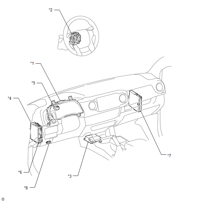
ILLUSTRATION
|
*1 |
COMBINATION METER ASSEMBLY |
*2 |
SPIRAL CABLE WITH SENSOR SUB-ASSEMBLY |
|
*3 |
YAW RATE AND ACCELERATION SENSOR (AIRBAG SENSOR ASSEMBLY) |
*4 |
DRIVER SIDE JUNCTION BLOCK - ECU-IG NO. 2 FUSE - IG1 NO. 2 FUSE |
|
*5 |
SKID CONTROL BUZZER |
*6 |
MAIN BODY ECU (MULTIPLEX NETWORK BODY ECU) |
|
*7 |
ECM |
*8 |
DLC3 |
 Precaution
PRECAUTION
PRECAUTION WHEN REPLACING COMBINATION METER ASSEMBLY
(a) When replacing the combination meter assembly, always replace it with a new
one. If a combination meter assembly which was insta ...
 System Description
SYSTEM DESCRIPTION
GENERAL DESCRIPTION
(a) The forward recognition camera processes the image captured by the monocular
camera to detect lane markers, vehicles, pedestrians, traffic signs, etc. Th ...
Other materials:
Removal
REMOVAL
CAUTION / NOTICE / HINT
HINT:
Use the same procedure for both the RH and LH sides.
The procedure described below is for the LH side.
PROCEDURE
1. PRECAUTION
CAUTION:
Be sure to read Precaution thoroughly before servicing (See page
).
NOTICE:
After turning the ign ...
Inspection
INSPECTION
PROCEDURE
1. REMOVE SPIRAL CABLE SUB-ASSEMBLY WITH SENSOR
(a) If there are any defects as mentioned below, replace the spiral cable sub-assembly
with a new one:
Scratches, cracks, dents or chips on the connector or the spiral cable sub-assembly.
(b) Inspect the spiral ca ...
Brake Warning Light does not Come ON
DESCRIPTION
The skid control ECU (brake actuator assembly) is connected to the combination
meter assembly via CAN communication.
WIRING DIAGRAM
Refer to Brake Warning Light Remains ON (See page
).
CAUTION / NOTICE / HINT
NOTICE:
When replacing the skid control ECU (brake actuator assembly) ...
