Toyota Tacoma (2015-2018) Service Manual: Parts Location
PARTS LOCATION
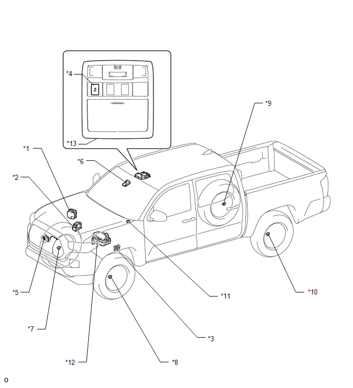
ILLUSTRATION
|
*1 |
SKID CONTROL ECU (BRAKE ACTUATOR ASSEMBLY) |
*2 |
THROTTLE BODY WITH MOTOR ASSEMBLY |
|
*3 |
PARK/NEUTRAL POSITION SWITCH |
*4 |
VSC OFF SWITCH |
|
*5 |
MILLIMETER WAVE RADAR SENSOR ASSEMBLY |
*6 |
FORWARD RECOGNITION CAMERA |
|
*7 |
FRONT SPEED SENSOR RH |
*8 |
FRONT SPEED SENSOR LH |
|
*9 |
REAR SPEED SENSOR RH |
*10 |
REAR SPEED SENSOR LH |
|
*11 |
SKID CONTROL BUZZER |
*12 |
ENGINE ROOM RELAY BLOCK - IG2 FUSE - STOP FUSE - STOP RELAY |
|
*13 |
ROOF CONSOLE BOX ASSEMBLY |
- |
- |
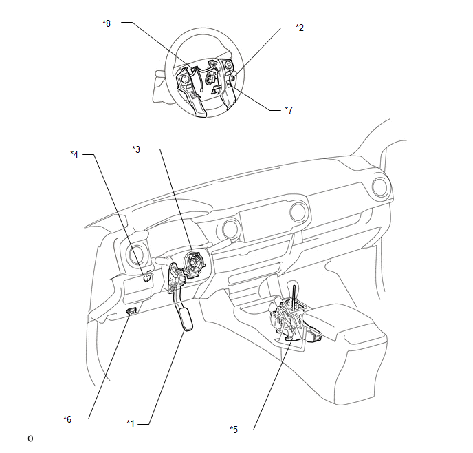
ILLUSTRATION
|
*1 |
ACCELERATOR PEDAL SENSOR ASSEMBLY |
*2 |
CRUISE CONTROL MAIN SWITCH |
|
*3 |
STEERING ANGLE SENSOR (SPIRAL CABLE WITH SENSOR SUB-ASSEMBLY) |
*4 |
STOP LIGHT SWITCH ASSEMBLY |
|
*5 |
TRANSMISSION CONTROL SWITCH (TRANSMISSION FLOOR SHIFT ASSEMBLY ) |
*6 |
DLC3 |
|
*7 |
DISTANCE CONTROL SWITCH (STEERING PAD SWITCH ASSEMBLY) |
*8 |
CRUISE CONTROL SWITCH WIRE |
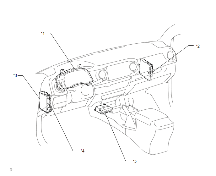
ILLUSTRATION
|
*1 |
COMBINATION METER ASSEMBLY |
*2 |
ECM |
|
*3 |
DRIVER SIDE JUNCTION BLOCK - IG1 NO. 2 FUSE - ECU-IG NO. 2 FUSE - IG1 NO. 1 FUSE - BKUP LP NO. 3 FUSE |
*4 |
MAIN BODY ECU (MULTIPLEX NETWORK BODY ECU) |
|
*5 |
YAW RATE AND ACCELERATION SENSOR (AIRBAG SENSOR ASSEMBLY) |
- |
- |

 Precaution
PRECAUTION
IGNITION SWITCH EXPRESSIONS
(a) The type of ignition switch used on this model differs according to the specifications
of the vehicle. The expressions listed in the table below are used ...
Other materials:
Touch Panel Switch does not Function
PROCEDURE
1.
CHECK MULTI-DISPLAY
(a) Check if there is any foreign matter caught between the display and exterior
frame of the multi-display.
OK:
No foreign matter is caught between the display and exterior frame of the multi-display.
HINT:
If there is foreig ...
On-vehicle Inspection
ON-VEHICLE INSPECTION
PROCEDURE
1. INSPECT PARK/NEUTRAL POSITION SWITCH
(a) Apply the parking brake.
(b) Turn the ignition switch to ON.
(c) Depress the brake pedal and move the shift lever to any position other than
P.
(d) Depress the brake pedal and check that the engine starts when the sh ...
Accessories, spare parts and modification of your Toyota
A wide variety of non-genuine spare parts and accessories for Toyota vehicles
are currently available in the market. You should know that Toyota does not warrant
these products and is not responsible for their performance, repair, or replacement,
or for any damage they may cause to, or adverse ...
