Toyota Tacoma (2015-2018) Service Manual: Terminals Of Ecu
TERMINALS OF ECU

CHECK MILLIMETER WAVE RADAR SENSOR ASSEMBLY
(a) Measure the voltage and resistance according to the value(s) in the table below.
|
Terminal No. (Symbol) |
Wiring Color |
Terminal Description |
Condition |
Specified Condition |
|---|---|---|---|---|
|
M8-8 (IGB) - M8-1 (SGND) |
LG - W-B |
Power source |
Ignition switch ON |
11 to 14 V |
|
M8-1 (SGND) - Body ground |
W-B - Body ground |
Ground |
Always |
Below 1 Ω |
(b) Check for pulses according to the value(s) in the table below.
HINT:
If the waveform is not similar to that shown in the illustration, malfunction of a CAN bus line, terminating resistor or the millimeter wave radar sensor assembly is suspected.
|
Terminal No. (Symbol) |
Wiring Color |
Terminal Description |
Condition |
Specified Condition |
|---|---|---|---|---|
|
M8-3 (CA2H) - M8-1 (SGND) |
W-B - W-B |
CAN communication signal |
Ignition switch ON |
Pulse generation (See waveform 1) |
|
M8-2 (CA2L) - M8-1 (SGND) |
W - W-B |
CAN communication signal |
Ignition switch ON |
Pulse generation (See waveform 2) |
|
M8-5 (CA1P) - M8-1 (SGND) |
B - W-B |
CAN communication signal |
Ignition switch ON |
Pulse generation (See waveform 1) |
|
M8-6 (CA1N) - M8-1 (SGND) |
W - W-B |
CAN communication signal |
Ignition switch ON |
Pulse generation (See waveform 2) |
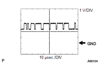
(1) Waveform 1
|
Item |
Content |
|---|---|
|
Terminal Name |
Between M8-3 (CA2H) and M8-1 (SGND) Between M8-5 (CA1P) and M8-1 (SGND) |
|
Tester Range |
1 V/DIV., 10 ÎĽsec./DIV. |
|
Condition |
Ignition switch ON |
HINT:
The waveform varies depending on the CAN communication signal.
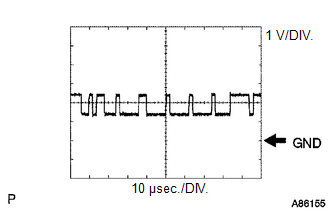
(2) Waveform 2
|
Item |
Content |
|---|---|
|
Terminal Name |
Between M8-2 (CA2L) and M8-1 (SGND) Between M8-6 (CA1N) and M8-1 (SGND) |
|
Tester Range |
1 V/DIV., 10 ÎĽsec./DIV. |
|
Condition |
Ignition switch ON |
HINT:
The waveform varies depending on the CAN communication signal.
NOTICE:
- DTCs may be stored when connectors are disconnected during inspection. Therefore, be sure to clear the DTCs using the Techstream once the inspection has been completed.
- Do not apply excessive force to the F46 forward recognition camera connector.

CHECK FORWARD RECOGNITION CAMERA
(a) Measure the voltage and resistance according to the value(s) in the table below.
|
Terminal No. (Symbol) |
Wiring Color |
Terminal Description |
Condition |
Specified Condition |
|---|---|---|---|---|
|
F46-7 (IGB) - F46-10 (GND) |
BE - W-B |
Power source |
Ignition switch ON |
11 to 14 V |
|
Ignition switch off |
Below 1 V |
|||
|
F46-10 (GND) - Body ground |
W-B - Body ground |
Ground |
Always |
Below 1 Ω |
(b) Check for pulses according to the value(s) in the table below.
HINT:
If the waveform is not similar to that shown in the illustration, malfunction of a CAN bus line, terminating resistor or the forward recognition camera is suspected.
|
Terminal No. (Symbol) |
Wiring Color |
Terminal Description |
Condition |
Specified Condition |
|---|---|---|---|---|
|
F46-5 (CA1P) - F46-10 (GND) |
L - W-B |
CAN communication signal |
Ignition switch ON |
Pulse generation (See waveform 1) |
|
F46-11 (CA1N) - F46-10 (GND) |
W - W-B |
CAN communication signal |
Ignition switch ON |
Pulse generation (See waveform 2) |
|
F46-6 (CANH) - F46-10 (GND) |
B - W-B |
CAN communication signal |
Ignition switch ON |
Pulse generation (See waveform 1) |
|
F46-12 (CANL) - F46-10 (GND) |
W - W-B |
CAN communication signal |
Ignition switch ON |
Pulse generation (See waveform 2) |
(1) Waveform 1
|
Item |
Content |
|---|---|
|
Terminal Name |
Between F46-5 (CA1P) and F46-10 (GND) Between F46-6 (CANH) and F46-10 (GND) |
|
Tester Range |
1 V/DIV., 10 ÎĽsec./DIV. |
|
Condition |
Ignition switch ON |
HINT:
The waveform varies depending on the CAN communication signal.
(2) Waveform 2
|
Item |
Content |
|---|---|
|
Terminal Name |
Between F46-11 (CA1N) and F46-10 (GND) Between F46-12 (CANL) and F46-10 (GND) |
|
Tester Range |
1 V/DIV., 10 ÎĽsec./DIV. |
|
Condition |
Ignition switch ON |
HINT:
The waveform varies depending on the CAN communication signal.
 Problem Symptoms Table
PROBLEM SYMPTOMS TABLE
HINT:
Use the table below to help determine the cause of problem symptoms.
If multiple suspected areas are listed, the potential causes of the symptoms
are lis ...
 Utility
UTILITY
NOTICE:
When replacing the millimeter wave radar sensor assembly, always replace
it with a new one. If a millimeter wave radar sensor assembly which was
installed to another ...
Other materials:
Inspection
INSPECTION
PROCEDURE
1. INSPECT TIRES
(a) Check the tires for wear and proper inflation pressure.
Standard Cold Tire Inflation Pressure:
Tire Size
Front Wheel
kPa (kgf/cm2, psi)
Rear Wheel
kPa (kgf/cm2, psi)
Spare Wheel
kPa (kgf/cm2, psi)
...
Seat Belt Buckle Switch LH Circuit Malfunction (B1656/38)
DESCRIPTION
The seat belt buckle switch LH circuit consists of the airbag sensor assembly
and the front seat inner belt assembly LH (seat belt buckle switch LH).
DTC B1655/37 is stored when a malfunction is detected in the seat belt buckle
switch LH circuit.
DTC No.
DTC ...
Manual Transmission Oil
Components
COMPONENTS
ILLUSTRATION
On-vehicle Inspection
ON-VEHICLE INSPECTION
PROCEDURE
1. INSPECT MANUAL TRANSMISSION OIL
(a) Park the vehicle on a level surface.
(b) Remove the transmission filler plug and gasket.
(c) Check that the oil level is between 0 to 5 mm (0 to 0 ...
