Toyota Tacoma (2015-2018) Service Manual: Parking Brake Switch
Components
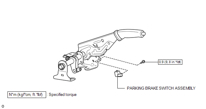
COMPONENTS
ILLUSTRATION
Inspection
INSPECTION
PROCEDURE
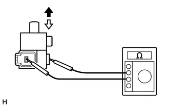
1. INSPECT PARKING BRAKE SWITCH ASSEMBLY
(a) Check the resistance.
(1) Measure the resistance according to the value(s) in the table below.
 Text in Illustration
 |
On |
.png) |
Off |
Standard Resistance:
|
Tester Connection |
Switch Condition |
Specified Condition |
|---|---|---|
|
Switch connector terminal - Switch body |
On (Shaft not pressed) |
Below 1 Ω |
|
Off (Shaft pressed) |
10 kΩ or higher |
If the result is not as specified, replace the parking brake switch assembly.
Installation
INSTALLATION
PROCEDURE
1. INSTALL PARKING BRAKE SWITCH ASSEMBLY
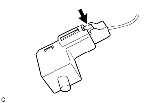
(a) Connect the connector to the parking brake switch assembly.
(b) Install the parking brake switch assembly to the parking brake lever with the screw.
Torque:
0.9 N·m {9 kgf·cm, 8 in·lbf}
2. INSTALL REAR CONSOLE BOX ASSEMBLY
(See page .gif) )
)
Removal
REMOVAL
PROCEDURE
1. REMOVE REAR CONSOLE BOX ASSEMBLY
(See page .gif) )
)
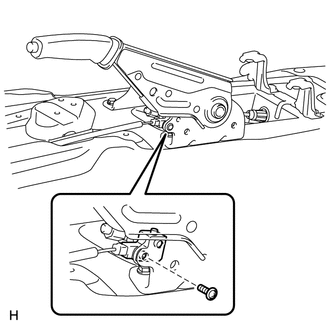
2. REMOVE PARKING BRAKE SWITCH ASSEMBLY
|
(a) Remove the screw and parking brake switch assembly from the parking brake lever. |
|
|
(b) Disconnect the connector. |
|
 Parking Brake Lever
Components
COMPONENTS
ILLUSTRATION
ILLUSTRATION
Installation
INSTALLATION
PROCEDURE
1. INSTALL PARKING BRAKE SWITCH ASSEMBLY
2. INSTALL PARKING BRAKE LEVER SUB-ASSEMBLY
(a) Install ...
 Parking Brake System
Adjustment
ADJUSTMENT
PROCEDURE
1. INSPECT PARKING BRAKE LEVER TRAVEL
(a) Fully pull the parking brake lever to engage the parking brake.
(b) Release the lever to disengage the parking brake.
...
Other materials:
Precaution
PRECAUTION
1. IGNITION SWITCH EXPRESSIONS
(a) The type of ignition switch used on this model differs according to the specifications
of the vehicle. The expressions listed in the table below are used in this section.
Expression
Ignition Switch (Position)
Engine ...
Poor Sound Quality in All Modes (Low Volume)
PROCEDURE
1.
CHECK AUDIO SETTINGS
(a) Set Treble, Mid and Bass to the initial values and check that sound is normal.
OK:
Malfunction disappears.
HINT:
Sound quality adjustment measures vary according to the type of amplifier.
OK
END
...
Vehicle Control History
VEHICLE CONTROL HISTORY
1. Function Overview
(a) The vehicle control history is a function that records control data (record
data) when triggered by specific vehicle behavior. When DTCs are not detected according
to information provided by customers, by checking the vehicle control history, it ...
