Toyota Tacoma (2015-2018) Service Manual: Disassembly
DISASSEMBLY
PROCEDURE
1. REMOVE STARTER YOKE ASSEMBLY
|
(a) Remove the nut and disconnect the lead wire from terminal C. |
|
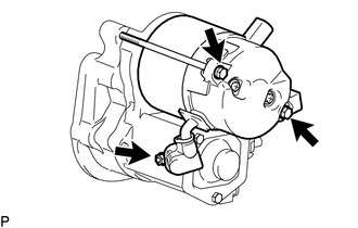
(b) Remove the 2 bolts.
(c) Pull out the starter yoke assembly and commutator end frame together with the starter armature assembly.
(d) Remove the O-ring from the starter yoke.
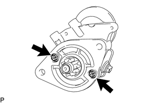
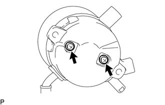
2. REMOVE MAGNET STARTER SWITCH ASSEMBLY
|
(a) Remove the 2 bolts and magnet starter switch assembly. |
|
|
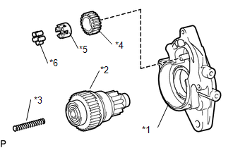
(b) Remove the idle gear, retainer, clutch roller, return spring and starter clutch sub-assembly from the starter drive housing assembly. Text in Illustration
|
|
|
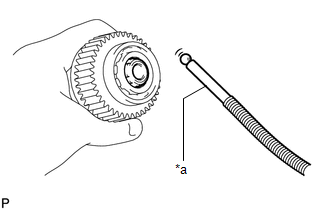
(c) Using a magnet hand, remove the steel ball from the starter clutch hole. Text in Illustration
|
|
3. REMOVE STARTER BRUSH HOLDER ASSEMBLY
|
(a) Remove the 2 screws and commutator end frame from the starter yoke assembly. NOTICE: While holding down the lead wire, remove the commutator end frame. |
|
(b) Remove the O-ring from the starter yoke assembly.
|
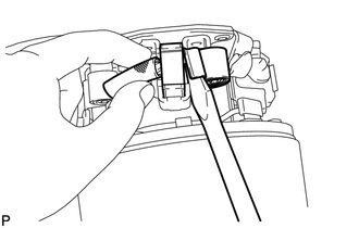
(c) Disconnect the 4 brushes from the starter brush holder assembly. (1) Using a screwdriver, hold back the brush spring. (2) Disconnect the brush from the starter brush holder assembly. |
|
(d) Remove the starter brush holder assembly.
4. REMOVE STARTER ARMATURE ASSEMBLY
(a) Remove the starter armature assembly from the starter yoke assembly.
 Components
COMPONENTS
ILLUSTRATION
ILLUSTRATION
...
 Inspection
INSPECTION
PROCEDURE
1. INSPECT MAGNET STARTER SWITCH ASSEMBLY
(a) Inspect the pull-in coil.
(1) Measure the resistance according to the value(s) in the table below.
Text in Illustra ...
Other materials:
List of storage features
Glove box
Overhead console (Access Cab and
Double Cab models)
Bottle holders
Auxiliary boxes
Front console box (separated type
front seat only)
Cup holders
CAUTION
■Items that should not be left in the storage spaces
Do not leave glasses, lighters or spray cans in the stora ...
Installation
INSTALLATION
PROCEDURE
1. INSTALL AIR CONDITIONING UNIT ASSEMBLY
(a) Temporary install the air conditioning unit assembly.
(b) Insert the bracket hook into the holes of the reinforcement bracket, and
temporary install the instrument panel reinforcement assembly.
(c) Install the instrument p ...
Clutch Accumulator
Components
COMPONENTS
ILLUSTRATION
Installation
INSTALLATION
PROCEDURE
1. INSTALL CLUTCH ACCUMULATOR ASSEMBLY
(a) Install the clutch accumulator assembly to the manual transmission assembly
with the 3 bolts.
Torque:
12 N·m {120 kgf·cm, 9 ft·lbf}
(b) Using a union nut wrench, co ...
