Toyota Tacoma (2015-2018) Service Manual: Open or Short in Rear Speed Sensor RH Circuit (C1407,C1408)
DESCRIPTION
Refer to DTCs C1403 and C1404 (See page .gif) ).
).
|
DTC No. |
Detection Item |
DTC Detection Condition |
Trouble Area |
|---|---|---|---|
|
C1407 |
Open or Short in Rear Speed Sensor RH Circuit |
Either of the following is detected:
|
|
|
C1408 |
Open or Short in Rear Speed Sensor LH Circuit |
Either of the following is detected:
|
|
HINT:
DTC will be output when conditions for either of the patterns in the table above are met.
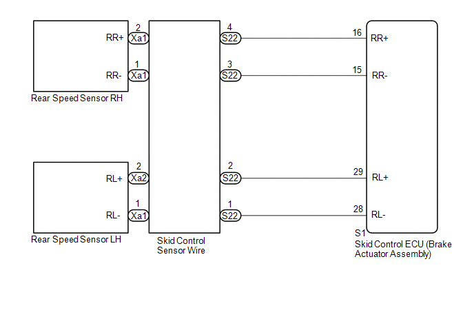
WIRING DIAGRAM
CAUTION / NOTICE / HINT
NOTICE:
When replacing the skid control ECU (brake actuator assembly), perform zero point
calibration and store system information (See page
).
PROCEDURE
|
1. |
CHECK HARNESS AND CONNECTOR (MOMENTARY INTERRUPTION) |
(a) Using the Techstream, check for any momentary interruption in the wire harness
and connector corresponding to the DTC (See page
).
|
Tester Display |
Measurement Item |
Normal Condition |
Diagnostic Note |
|---|---|---|---|
|
RR Speed Open |
Rear speed sensor RH open circuit detection/ Error or Normal |
Normal |
Error: Momentary interruption |
|
RL Speed Open |
Rear speed sensor LH open circuit detection/ Error or Normal |
Normal |
Error: Momentary interruption |
OK:
Normal (There are no momentary interruptions.)
HINT:
Perform the above inspection before removing the sensor and connector.
| NG | .gif) |
GO TO STEP 4 |
|
.gif)
|
2. |
READ VALUE USING TECHSTREAM (REAR SPEED SENSOR) |
(a) Turn the ignition switch off.
(b) Connect the Techstream to the DLC3.
(c) Start the engine.
(d) Turn the Techstream on.
(e) Enter the following menus: Chassis / ABS/VSC/TRAC / Data List.
(f) According to the display on the Techstream, read the Data List.
ABS/VSC/TRAC|
Tester Display |
Measurement Item |
Normal Condition |
Diagnostic Note |
|---|---|---|---|
|
RR Wheel Speed |
Rear wheel speed sensor RH reading/ Min.: 0 km/h (0 mph), Max.: 326 km/h (202 mph) |
Vehicle stopped: 0 km/h (0 mph) |
When driving at constant speed: No large fluctuations |
|
RL Wheel Speed |
Rear wheel speed sensor LH reading/ Min.: 0 km/h (0 mph), Max.: 326 km/h (202 mph) |
Vehicle stopped: 0 km/h (0 mph) |
When driving at constant speed: No large fluctuations |
(g) Check that there is no difference between the speed value output from the speed sensor displayed on the Techstream and the speed value displayed on the speedometer when driving the vehicle.
HINT:
Factors that affect the indicated vehicle speed include tire size, tire inflation
and tire wear. The speed indicated on the speedometer has an allowable margin of
error. This can be tested using a speedometer tester (calibrated chassis dynamometer).
For details about testing and the margin of error, see the reference chart (See
page ).
OK:
The speed value output from the speed sensor displayed on the Techstream is the same as the actual vehicle speed measured using a speedometer tester (calibrated chassis dynamometer).
NOTICE:
Check the speed sensor signal after replacement (See page
).
HINT:
If troubleshooting has been carried out according to the Problem Symptoms Table,
refer back to the table and proceed to the next step (See page
).
| NG | |
GO TO STEP 4 |
|
|
3. |
RECONFIRM DTC |
(a) Clear the DTCs (See page
).
(b) Turn the ignition switch off.
(c) Start the engine.
(d) Perform a road test.
(e) Check if the same DTC is recorded (See page
).
|
Result |
Proceed to |
|---|---|
|
DTCs C1407 and C1408 are not output |
A |
|
DTCs C1407 and/or C1408 are output |
B |
| A | |
USE SIMULATION METHOD TO CHECK |
| B | |
REPLACE BRAKE ACTUATOR ASSEMBLY |
|
4. |
INSPECT SKID CONTROL SENSOR WIRE |
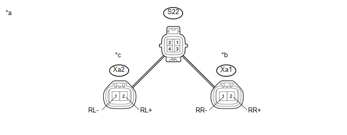 Text in Illustration
|
*a |
Skid Control Sensor Wire |
- |
- |
|
*b |
for RH |
*c |
for LH |
(a) Remove the skid control sensor wire (See page
).
(b) Measure the resistance according to the value(s) in the table below.
Standard Resistance:
for RH|
Tester Connection |
Condition |
Specified Condition |
|---|---|---|
|
S22-4 - Xa1-2 (RR+) |
Always |
Below 1 Ω |
|
S22-3 - Xa1-1 (RR-) |
Always |
Below 1 Ω |
|
S22-4 - S22-3 |
Always |
10 kΩ or higher |
|
S22-4 - S22-1 |
Always |
10 kΩ or higher |
|
S22-4 - S22-2 |
Always |
10 kΩ or higher |
|
Tester Connection |
Condition |
Specified Condition |
|---|---|---|
|
S22-2 - Xa2-2 (RL+) |
Always |
Below 1 Ω |
|
S22-1 - Xa2-1 (RL-) |
Always |
Below 1 Ω |
|
S22-2 - S22-1 |
Always |
10 kΩ or higher |
|
S22-2 - S22-3 |
Always |
10 kΩ or higher |
|
S22-2 - S22-4 |
Always |
10 kΩ or higher |
| NG | |
REPLACE SKID CONTROL SENSOR WIRE |
|
|
5. |
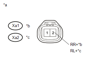
CHECK HARNESS AND CONNECTOR (BRAKE ACTUATOR ASSEMBLY - REAR SPEED SENSOR) |
(a) Turn the ignition switch off.
(b) Make sure that there is no looseness at the locking part and the connecting part of the connectors.
(c) Disconnect the S1 skid control ECU (brake actuator assembly) connector and the O3 and/or O4 rear speed sensor connector.
(d) Measure the resistance according to the value(s) in the table below.
Standard Resistance:
for RH|
Tester Connection |
Condition |
Specified Condition |
|---|---|---|
|
S1-16 (RR+) - Xa1-2 (RR+) |
Always |
Below 1 Ω |
|
S1-15 (RR-) - Xa1-1 (RR-) |
Always |
Below 1 Ω |
|
S1-16 (RR+) or Xa1-2 (RR+) - Body ground |
Always |
10 kΩ or higher |
|
S1-15 (RR-) or Xa1-1 (RR-) - Body ground |
Always |
10 kΩ or higher |
|
Tester Connection |
Condition |
Specified Condition |
|---|---|---|
|
S1-29 (RL+) - Xa2-2 (RL+) |
Always |
Below 1 Ω |
|
S1-28 (RL-) - Xa2-1 (RL-) |
Always |
Below 1 Ω |
|
S1-29 (RL+) or Xa2-2 (RL+) - Body ground |
Always |
10 kΩ or higher |
|
S1-28 (RL-) or Xa2-1 (RL- ) - Body ground |
Always |
10 kΩ or higher |
| NG | |
REPAIR OR REPLACE HARNESS OR CONNECTOR |
|
|
6. |
INSPECT BRAKE ACTUATOR ASSEMBLY (SENSOR INPUT) |
(a) Reconnect the S1 skid control ECU (brake actuator assembly) connector.
(b) Turn the ignition switch to ON.
|
(c) Measure the voltage according to the value(s) in the table below. Standard Voltage: for RH
NOTICE: Check the speed sensor signal after replacement (See page
|
|
| OK | |
REPLACE REAR SPEED SENSOR |
| NG | |
REPLACE BRAKE ACTUATOR ASSEMBLY |
 Open or Short in Front Speed Sensor RH Circuit (C1405,C1406)
DESCRIPTION
Refer to DTCs C1401 and C1402 (See page ).
DTC No.
Detection Item
DTC Detection Condition
Trouble Area
C1405
Open ...
 Front Speed Sensor RH Output Malfunction (C1413,C1414)
DESCRIPTION
Refer to DTCs C1401 and C1402 (See page ).
DTC No.
Detection Item
DTC Detection Condition
Trouble Area
C1413
Fron ...
Other materials:
Removal
REMOVAL
PROCEDURE
1. REMOVE REAR SEAT CUSHION ASSEMBLY
(a) Remove the 2 bolts and rear seat cushion assembly.
2. REMOVE REAR SEATBACK HINGE COVER
(a) for LH Side:
(1) Disengage the 6 claws to remove the 2 rear seatback hinge cov ...
Maintenance data (fuel, oil level, etc.)
Dimensions
2WD models except PreRunner
*: Unladen vehicle
4WD models and PreRunner (except
Regular Cab models)
*: Unladen vehicle
*: Unladen vehicle
Vehicle capacity weight
2WD models except PreRunner
*: Installing accessories in addition to those installed at the factory increase ...
Data List / Active Test
DATA LIST / ACTIVE TEST
NOTICE:
In the table below, the values listed under "Normal Condition" are reference
values. Do not depend solely on these reference values when deciding whether a part
is faulty or not.
HINT:
Using the Techstream to read the Data List allows the values or s ...
