Toyota Tacoma (2015-2018) Service Manual: Removal
REMOVAL
PROCEDURE
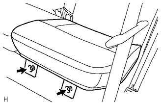
1. REMOVE REAR SEAT CUSHION ASSEMBLY
|
(a) Remove the 2 bolts and rear seat cushion assembly. |
|
2. REMOVE REAR SEATBACK HINGE COVER
|
(a) for LH Side: (1) Disengage the 6 claws to remove the 2 rear seatback hinge covers. |
|
(b) for RH Side:
(1) Remove the rear seatback hinge cover (See page
.gif) ).
).
3. REMOVE REAR SEATBACK ASSEMBLY LH
|
(a) Remove the 2 bolts and rear seatback assembly LH. |
|
4. REMOVE REAR SEATBACK ASSEMBLY RH
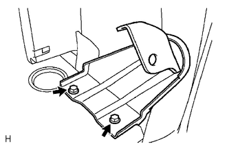
5. REMOVE REAR SEATBACK HINGE SUB-ASSEMBLY
|
(a) Remove the 2 bolts and rear seatback hinge sub-assembly. |
|
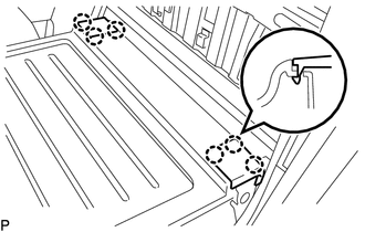
6. REMOVE LUGGAGE COMPARTMENT SIDE TRAY
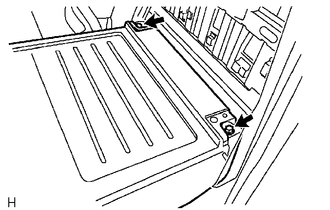
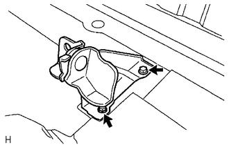
7. REMOVE REAR SEATBACK CENTER HINGE SUB-ASSEMBLY
|
(a) Remove the 2 bolts and rear seatback center hinge sub-assembly. |
|
 Components
COMPONENTS
ILLUSTRATION
ILLUSTRATION
...
 Disassembly
DISASSEMBLY
CAUTION / NOTICE / HINT
CAUTION:
Wear protective gloves. Sharp areas on the parts may injure your hands.
PROCEDURE
1. REMOVE REAR SEAT CUSHION BAND
(a) Remove the screw an ...
Other materials:
Diagnosis System
DIAGNOSIS SYSTEM
1. CHECK DLC3
(a) The vehicle ECUs use ISO 15765-4 communication protocol. The terminal arrangement
of the DLC3 complies with ISO 15031-3 and matches the ISO 15765-4 format.
Terminals No. (Symbols)
Terminal Description
Condition
Spe ...
Terminals Of Ecu
TERMINALS OF ECU
1. TERMINAL INSPECTION
Text in Illustration
*a
Component without harness connected
(Steering Lock ECU (Steering Lock Actuator or UPR Bracket Assembly))
-
-
(a) Measure the voltage and resistance according to the value(s) i ...
Parts Location
PARTS LOCATION
ILLUSTRATION
ILLUSTRATION
ILLUSTRATION
ILLUSTRATION
...
