Toyota Tacoma (2015-2018) Service Manual: Inspection
INSPECTION
PROCEDURE
1. INSPECT INPUT SHAFT
|
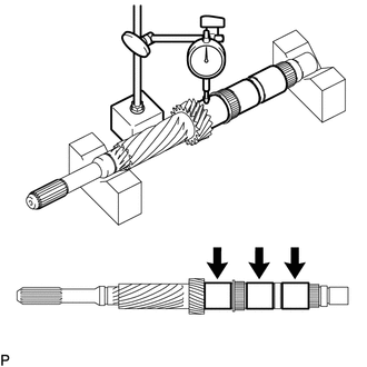
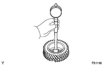
(a) Using a dial indicator and 2 V-blocks, measure the shaft runout. Maximum runout: 0.03 mm (0.0012 in.) If the runout is more than the maximum, replace the input shaft. HINT: Measure the 3 areas shown in the illustration with the input shaft level. |
|
|
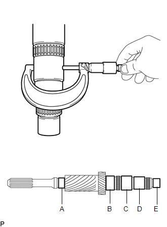
(b) Using a micrometer, measure the journal diameter of each input shaft journal at the specified positions. Standard Journal Diameter:
Minimum Diameter:
If the journal diameter is less than the minimum, replace the input shaft. |
|
2. INSPECT 5TH GEAR
|
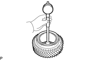
(a) Using a cylinder gauge, measure the inside diameter of the 5th gear. Standard inside diameter: 53.013 to 53.029 mm (2.0872 to 2.0877 in.) Maximum inside diameter: 53.029 mm (2.0877 in.) If the inside diameter is more than the maximum, replace the 5th gear. |
|
3. INSPECT 6TH GEAR SUB-ASSEMBLY
|
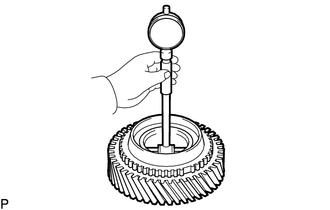
(a) Using a cylinder gauge, measure the inside diameter of the 6th gear sub-assembly. Standard inside diameter: 51.015 to 51.040 mm (2.0085 to 2.0094 in.) Maximum inside diameter: 51.040 mm (2.0094 in.) If the inside diameter is more than the maximum, replace the 6th gear sub-assembly. |
|
4. INSPECT 3RD GEAR
|
(a) Using a cylinder gauge, measure the inside diameter of the 3rd gear. Standard inside diameter: 51.015 to 51.040 mm (2.0085 to 2.0094 in.) Maximum inside diameter: 51.040 mm (2.0094 in.) If the inside diameter is more than the maximum, replace the 3rd gear. |
|
5. INSPECT NO. 2 TRANSMISSION HUB SLEEVE
|
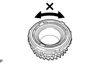
(a) Check the sliding condition between the No. 2 transmission hub and No. 2 transmission hub sleeve. |
|
(b) Check that the splines of the No. 2 transmission hub sleeve are not worn.
|
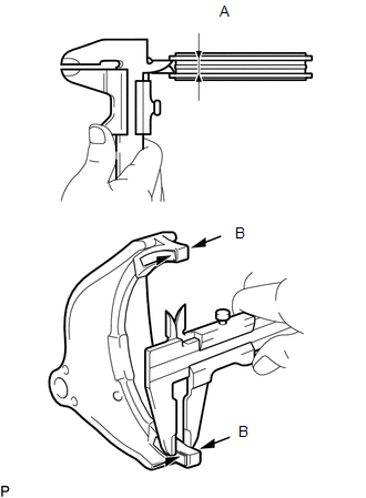
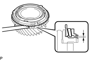
(c) Using a vernier caliper, measure the width of the No. 2 transmission hub sleeve groove (A) and the thickness of the claw part of the No. 2 or No. 3 gear shift forks (B), and calculate the clearance. Standard Clearance (A - B):
If the clearance is outside the specification, replace the No. 2 transmission hub sleeve and gear shift fork. |
|
6. INSPECT NO. 3 SYNCHRONIZER RING (for 5th Gear)
|
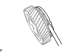
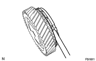
(a) Using a feeler gauge, measure the clearance between the No. 3 synchronizer ring and 5th gear. Standard clearance: 0.77 to 1.63 mm (0.0304 to 0.0641 in.) Minimum clearance: 0.77 mm (0.0304 in.) If the clearance is less than the minimum, replace the synchronizer ring. |
|
(b) Coat the 5th gear cone with gear oil.
|
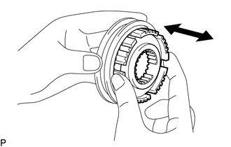
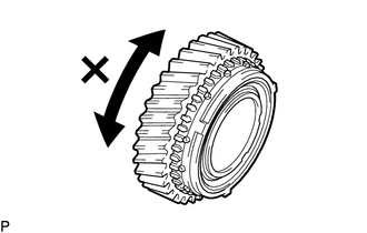
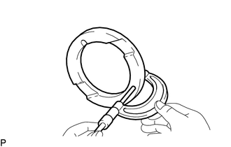
(c) Check the braking effect of the synchronizer ring. (1) Turn the synchronizer ring in both directions while pushing it against the 5th gear cone. Check that the ring locks in both directions. If the No. 3 synchronizer ring turns, replace it. |
|
7. INSPECT NO. 3 SYNCHRONIZER RING (for 6th Gear)
|
(a) Using a feeler gauge, measure the clearance between the No. 3 synchronizer ring and 6th gear. Standard clearance: 0.77 to 1.63 mm (0.0304 to 0.0641 in.) Minimum clearance: 0.77 mm (0.0304 in.) If the clearance is less than the minimum, replace the synchronizer ring. |
|
(b) Coat the 6th gear cone with gear oil.
|
(c) Check the braking effect of the synchronizer ring. (1) Turn the synchronizer ring in both directions while pushing it against the 6th gear cone. Check that the ring locks in both directions. If the No. 3 synchronizer ring turns, replace it. |
|
8. INSPECT NO. 3 SYNCHRONIZER RING SET
|
(a) Using a feeler gauge, measure the clearance between the synchronizer ring and 3rd gear. Standard clearance: 0.86 to 2.02 mm (0.0339 to 0.0795 in.) Minimum clearance: 0.86 mm (0.0339 in.) If the clearance is less than the minimum, replace the No. 3 synchronizer ring set. |
|
(b) Coat the 3rd gear cone with gear oil.
|
(c) Check the braking effect of the synchronizer ring. (1) Turn the synchronizer ring in both directions while pushing it against the 3rd gear cone. Check that the ring locks in both directions. If the No. 3 synchronizer ring set turns, replace it. |
|
9. INSPECT 3RD GEAR THRUST WASHER
|
(a) Using a micrometer, measure the 3rd gear thrust washer thickness. Standard thickness: 7.62 to 7.68 mm (0.3000 to 0.3023 in.) Minimum thickness: 7.62 mm (0.3000 in.) If the thickness is less than the minimum, replace the 3rd gear thrust washer. |
|
 Disassembly
DISASSEMBLY
PROCEDURE
1. INSPECT 3RD GEAR THRUST CLEARANCE
(a) Using a dial indicator, measure the 3rd gear thrust clearance.
Standard clearance:
0.200 to 0.490 mm (0.0079 to 0.01 ...

Other materials:
Output Shaft
Components
COMPONENTS
ILLUSTRATION
Disassembly
DISASSEMBLY
PROCEDURE
1. REMOVE FRONT OUTPUT SHAFT BEARING
(a) Temporarily install the manual transmission output shaft rear set
nut to the output shaft.
Text in Illustration
*1
Manual ...
Precaution
PRECAUTION
1. IGNITION SWITCH EXPRESSIONS
(a) The type of ignition switch used on this model differs according to the specifications
of the vehicle. The expressions listed in the table below are used in this section.
Expression
Ignition Switch (Position)
Engine ...
Inspection
INSPECTION
PROCEDURE
1. INSPECT FRONT SUSPENSION LOWER ARM
(a) Flip the ball joint stud back and forth 5 times, as shown in the illustration,
before installing the nut.
(b) Using a torque wrench, turn the nut continuously at a rate of 2 to 4 seconds
per turn and take the torque reading on ...
