Toyota Tacoma (2015-2018) Service Manual: Open in Turn Signal Circuit (B1507,B1508)
DESCRIPTION
This DTC is stored when the combination meter assembly detects an open in a turn signal light circuit, a short in a turn signal light circuit, or a short in the hazard warning light circuit.
|
DTC No. |
DTC Detection Condition |
Trouble Area |
|---|---|---|
|
B1507 |
When IG voltage is 9.5 V or more and the following condition is detected:
|
|
|
B1508 |
When IG voltage is more than 7 V and the following condition is detected:
|
|
- *: except Trailer Towing System
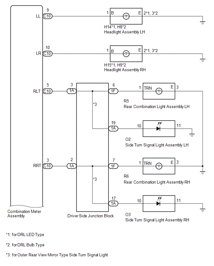
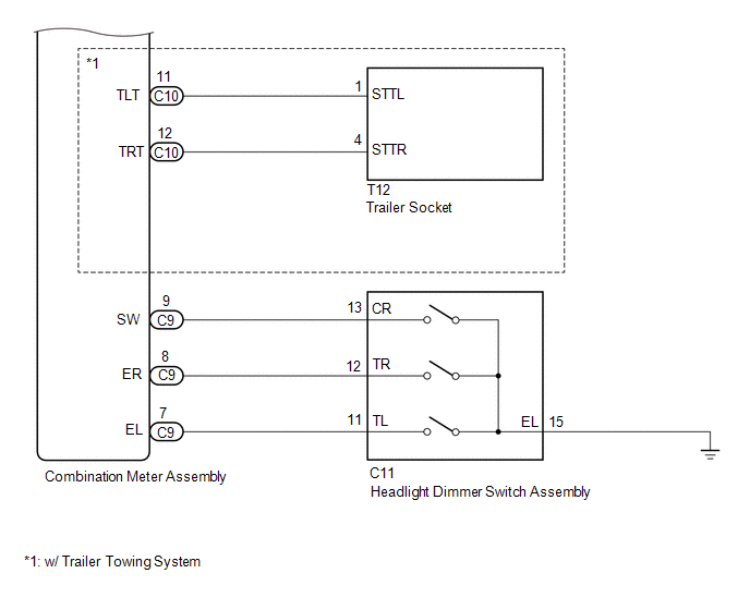
WIRING DIAGRAM
CAUTION / NOTICE / HINT
NOTICE:
Inspect the bulbs for circuits related to this system before performing the following inspection procedure.
PROCEDURE
|
1. |
INSPECT LIGHTS |
(a) Inspect the illumination of each turn signal light.
Result|
Result |
Proceed to |
|---|---|
|
Turn signal lights for one side do not illuminate (except Front Turn Signal Light) |
A |
|
Front turn signal light does not illuminate |
B |
|
Rear turn signal light does not illuminate |
C |
|
Side turn signal light does not illuminate (for Outer Rear View Mirror Type Side Turn Signal Light) |
D |
|
Trailer turn signal light does not illuminate (w/ Trail Towing System |
E |
| B | .gif) |
GO TO STEP 3 |
| C | |
GO TO STEP 4 |
| D | |
GO TO STEP 5 |
| E | |
GO TO STEP 6 |
|
.gif)
|
2. |
CHECK HARNESS AND CONNECTOR (COMBINATION METER ASSEMBLY - DRIVER SIDE JUNCTION BLOCK) |
(a) Disconnect the C10 combination meter assembly connector.
(b) Disconnect the 1A driver side junction block connector.
(c) Measure the resistance according to the value(s) in the table below.
Standard Resistance:
|
Tester Connection |
Condition |
Specified Condition |
|---|---|---|
|
C10-5 (RLT) - 1A-3 |
Always |
Below 1 Ω |
|
C10-5 (RLT) or 1A-3 - Body ground |
Always |
10 kΩ or higher |
|
C10-3 (RRT) - 1A-2 |
Always |
Below 1 Ω |
|
C10-3 (RRT) or 1A-2 - Body ground |
Always |
10 kΩ or higher |
|
Result |
Proceed to |
|---|---|
|
NG |
A |
|
OK |
B |
| A | |
REPAIR OR REPLACE HARNESS OR CONNECTOR |
| B | |
GO TO STEP 7 |
|
3. |
CHECK HARNESS AND CONNECTOR (HEADLIGHT ASSEMBLY - COMBINATION METER ASSEMBLY) |
(a) for DRL LED Type:
(1) Disconnect the H14 headlight assembly LH connectors.
(2) Disconnect the H15 headlight assembly RH connectors.
(3) Disconnect the C10 combination meter assembly connector.
(4) Measure the resistance according to the value(s) in the table below.
Standard Resistance:
|
Tester Connection |
Condition |
Specified Condition |
|---|---|---|
|
H14-1 (B) - C10-9 (LL) |
Always |
Below 1 Ω |
|
H14-2 (E) - Body ground |
Always |
Below 1 Ω |
|
H14-1 (B) or C10-9 (LL) - Body ground |
Always |
10 kΩ or higher |
|
H15-1 (B) - C10-10 (LR) |
Always |
Below 1 Ω |
|
H15-2 (E) - Body ground |
Always |
Below 1 Ω |
|
H15-1 (B) or C10-10 (LR) - Body ground |
Always |
10 kΩ or higher |
(b) for DRL Bulb Type:
(1) Disconnect the H8 headlight assembly LH connectors.
(2) Disconnect the H9 headlight assembly RH connectors.
(3) Disconnect the C10 combination meter assembly connector.
(4) Measure the resistance according to the value(s) in the table below.
Standard Resistance:
|
Tester Connection |
Condition |
Specified Condition |
|---|---|---|
|
H8-1 (B) - C10-9 (LL) |
Always |
Below 1 Ω |
|
H8-2 (E) - Body ground |
Always |
Below 1 Ω |
|
H8-1 (B) or C10-9 (LL) - Body ground |
Always |
10 kΩ or higher |
|
H9-1 (B) - C10-10 (LR) |
Always |
Below 1 Ω |
|
H9-2 (E) - Body ground |
Always |
Below 1 Ω |
|
H9-1 (B) or C10-10 (LR) - Body ground |
Always |
10 kΩ or higher |
| OK | |
REPLACE COMBINATION METER ASSEMBLY |
| NG | |
REPAIR OR REPLACE HARNESS OR CONNECTOR |
|
4. |
CHECK HARNESS AND CONNECTOR (REAR COMBINATION LIGHT ASSEMBLY - DRIVER SIDE JUNCTION BLOCK) |
(a) Disconnect the R5 rear combination light assembly LH connector.
(b) Disconnect the R6 rear combination light assembly RH connector.
(c) Disconnect the 1F driver side junction block connector.
(d) Measure the resistance according to the value(s) in the table below.
Standard Resistance:
|
Tester Connection |
Condition |
Specified Condition |
|---|---|---|
|
R5-1 - 1F-6 |
Always |
Below 1 Ω |
|
R5-3 - Body ground |
Always |
Below 1 Ω |
|
R5-1 or 1F-6 - Body ground |
Always |
10 kΩ or higher |
|
R6-1 - 1F-7 |
Always |
Below 1 Ω |
|
R6-1 - Body ground |
Always |
Below 1 Ω |
|
R6-1 or 1F-7 - Body ground |
Always |
10 kΩ or higher |
|
Result |
Proceed to |
|---|---|
|
NG |
A |
|
OK |
B |
| A | |
REPAIR OR REPLACE HARNESS OR CONNECTOR |
| B | |
GO TO STEP 7 |
|
5. |
CHECK HARNESS AND CONNECTOR (OUTER REAR VIEW MIRROR ASSEMBLY - DRIVER SIDE JUNCTION BLOCK) |
(a) Disconnect the O2 outer rear view mirror assembly LH connector.
(b) Disconnect the O3 outer rear view mirror assembly RH connector.
(c) Disconnect the 1A driver side junction block connector.
(d) Measure the resistance according to the value(s) in the table below.
Standard Resistance:
|
Tester Connection |
Condition |
Specified Condition |
|---|---|---|
|
O2-10 - 1A-19 |
Always |
Below 1 Ω |
|
O2-11 - Body ground |
Always |
Below 1 Ω |
|
O2-10 or 1A-19 - Body ground |
Always |
10 kΩ or higher |
|
O3-10 - 1A-17 |
Always |
Below 1 Ω |
|
O3-11 - Body ground |
Always |
Below 1 Ω |
|
O3-10 or 1A-17 - Body ground |
Always |
10 kΩ or higher |
|
Result |
Proceed to |
|---|---|
|
NG |
A |
|
OK |
B |
| A | |
REPAIR OR REPLACE HARNESS OR CONNECTOR |
| B | |
GO TO STEP 7 |
|
6. |
CHECK HARNESS AND CONNECTOR (COMBINATION METER ASSEMBLY - TRAILER SOCKET) |
(a) Disconnect the C10 combination meter assembly connector.
(b) Disconnect the T12 trailer socket connector.
(c) Measure the resistance according to the value(s) in the table below.
Standard Resistance:
|
Tester Connection |
Condition |
Specified Condition |
|---|---|---|
|
C10-11(TLT) - T12-1(STTL) |
Always |
Below 1 Ω |
|
C10-12(TRT) - T12-4(STTR) |
Always |
Below 1 Ω |
|
C10-11(TLT) or T12-1(STTL) - Body ground |
Always |
10 kΩ or higher |
|
C10-12(TRT) or T12-4(STTR) - Body ground |
Always |
10 kΩ or higher |
| OK | |
REPLACE COMBINATION METER ASSEMBLY |
| NG | |
REPAIR OR REPLACE HARNESS OR CONNECTOR |
|
7. |
INSPECT DRIVER SIDE JUNCTION BLOCK |
(a) Remove the main body ECU (multiplex network body ECU) from the instrument
panel junction block assembly (See page .gif) ).
).
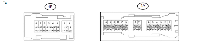 Text in Illustration
|
*a |
Component without harness connected (Driver Side Junction Block) |
- |
- |
(b) Measure the resistance according to the value(s) in the table below.
Standard Resistance:
|
Tester Connection |
Condition |
Specified Condition |
|---|---|---|
|
1A-3 - 1F-6 |
Always |
Below 1 Ω |
|
1A-3 - 1A-19*1 |
Always |
Below 1 Ω |
|
1A-2 - 1F-7 |
Always |
Below 1 Ω |
|
1A-2 - 1A-17*1 |
Always |
Below 1 Ω |
- *1: for Outer Rear View Mirror Type Side Turn Signal Light
| OK | |
REPLACE COMBINATION METER ASSEMBLY |
| NG | |
REPLACE DRIVER SIDE JUNCTION BLOCK |
 Fuel Sender Open Detected (B1500)
DESCRIPTION
This DTC is output when the combination meter assembly detects a fuel sender
gauge assembly malfunction.
DTC No.
DTC Detection Condition
Trouble Area
...
 Lost Communication with ECM / PCM "A" (U0100,U0129,U0142,U0151,U0163,U023A,U1104)
DESCRIPTION
The combination meter communicates with the ECM, skid control ECU, power steering
ECU, main body ECU (multiplex network body ECU), airbag sensor assembly, navigation
receiver assembly ...
Other materials:
Short to +B in Buzzer (C1ABD,C1ABE)
DESCRIPTION
DTC C1ABD is stored when the blind spot monitor sensor RH detects a
+B short in rear cross traffic alert buzzer (blind spot monitor buzzer)
circuit.
DTC C1ABE is stored when the blind spot monitor sensor RH detects a
ground short or open in rear cross traffic aler ...
FCM Destination Information Uninitialized (C1AAA)
DESCRIPTION
When the forward recognition camera is replaced with a new one, the new forward
recognition camera attempts to store the country specification information received
from the main body ECU (multiplex network body ECU). If the forward recognition
camera cannot store the country speci ...
Steering Angle Sensor (C1A47)
DESCRIPTION
The forward recognition camera receives steering angle information from the spiral
cable with sensor sub-assembly. If the forward recognition camera detects a spiral
cable with sensor sub-assembly malfunction, DTC C1A47 is stored.
DTC No.
Detection Item
...
