Toyota Tacoma (2015-2018) Service Manual: Components
COMPONENTS
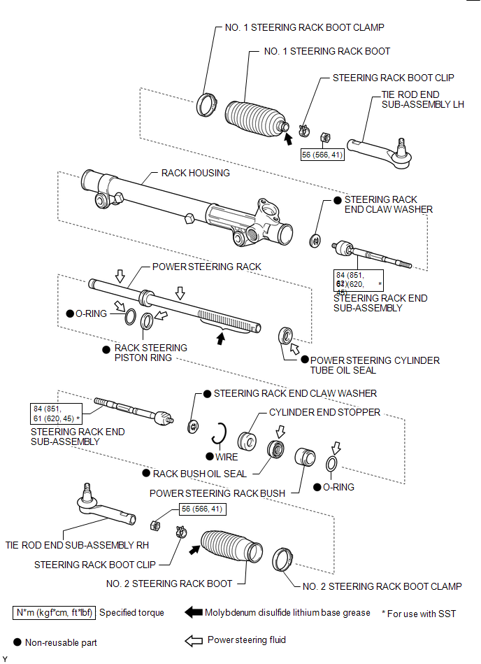
ILLUSTRATION
|
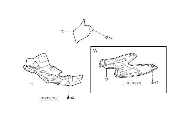
*A |
w/ Off Road Package |
- |
- |
|
*1 |
NO. 1 ENGINE UNDER COVER SUB-ASSEMBLY |
*2 |
NO. 2 ENGINE UNDER COVER SUB-ASSEMBLY |
|
*3 |
FRONT UPPER FENDER APRON SEAL |
- |
- |
.png) |
N*m (kgf*cm, ft.*lbf): Specified torque |
- |
- |
ILLUSTRATION
|
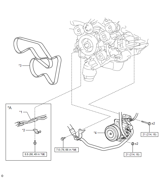
*A |
for Automatic Transmission |
- |
- |
|
*1 |
AUTOMATIC TRANSMISSION OIL COOLER TUBE |
*2 |
CLAMP |
|
*3 |
FAN AND GENERATOR V BELT |
*4 |
COOLER COMPRESSOR ASSEMBLY |
|
|
N*m (kgf*cm, ft.*lbf): Specified torque |
- |
- |
ILLUSTRATION
|
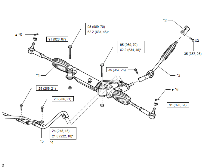
*1 |
POWER STEERING LINK |
*2 |
STEERING SLIDING YOKE |
|
*3 |
NO. 2 STEERING INTERMEDIATE SHAFT |
*4 |
PRESSURE FEED TUBE |
|
*5 |
RETURN HOSE |
*6 |
COTTER PIN |
|
|
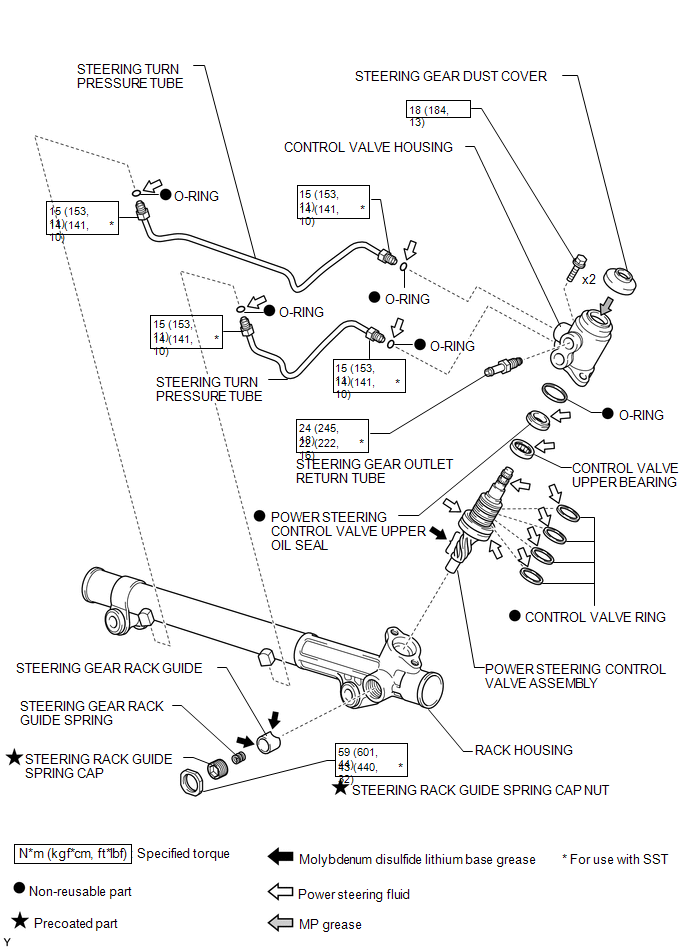
N*m (kgf*cm, ft.*lbf): Specified torque |
* |
For use with SST or a union nut wrench |
|
â—Ź |
Non-reusable part |
- |
- |
ILLUSTRATION
ILLUSTRATION

 Removal
REMOVAL
PROCEDURE
1. PLACE FRONT WHEELS FACING STRAIGHT AHEAD
2. REMOVE FRONT WHEELS
3. REMOVE FRONT UPPER FENDER APRON SEAL
Click here
4. REMOVE NO. 2 ENGINE UNDER COVER SUB-ASSEMBLY (w/ Of ...
Other materials:
System Description
SYSTEM DESCRIPTION
1. SYSTEM DESCRIPTION
(a) The Electronic Controlled Automatic Transmission (ECT) is an automatic transmission
that has its shift timing electronically controlled by the ECM. The ECM detects
electrical signals that indicate engine and driving conditions, and controls the
sh ...
Precaution
PRECAUTION
1. IGNITION SWITCH EXPRESSION
HINT:
The type of ignition switch used on this model differs depending on the specifications
of the vehicle. The expressions listed in the table below are used in this section.
Expression
Ignition Switch (Position)
Engin ...
Identification Information
Vehicle Identification And Serial Numbers
VEHICLE IDENTIFICATION AND SERIAL NUMBERS
1. VEHICLE IDENTIFICATION NUMBER
(a) The vehicle identification number is stamped on the vehicle body and on the
certification label, as shown in the illustration.
A:
Vehicle Identification Number
B:
C ...
