Toyota Tacoma (2015-2018) Service Manual: Fuel Sender Open Detected (B1500)
DESCRIPTION
This DTC is output when the combination meter assembly detects a fuel sender gauge assembly malfunction.
|
DTC No. |
DTC Detection Condition |
Trouble Area |
|---|---|---|
|
B1500 |
When either of the following conditions is detected:
|
|
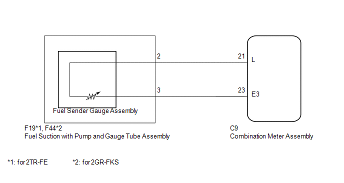
WIRING DIAGRAM
PROCEDURE
|
1. |
READ VALUE USING TECHSTREAM (FUEL INPUT) |
(a) Connect the Techstream to the DLC3.
(b) Turn the ignition switch to ON.
(c) Turn the Techstream on.
(d) Enter the following menus: Body Electrical / Combination Meter / Data List.
(e) According to the display on the Techstream, read the Data List.
Combination Meter|
Tester Display |
Measurement Item/Range |
Normal Condition |
Diagnostic Note |
|---|---|---|---|
|
Fuel Input |
Fuel input signal/ Min.: 0, Max.: 127.5 |
Current fuel level displayed |
Unit: Liter |
|
Result |
Proceed to |
|---|---|
|
Fuel level data can be displayed on the Techstream and DTC B1500 is output |
A |
|
Fuel level data cannot be displayed on the Techstream |
B |
| A | .gif) |
REPLACE COMBINATION METER ASSEMBLY |
|
.gif)
|
2. |
INSPECT FUEL SENDER GAUGE ASSEMBLY |
|
(a) Disconnect the combination meter assembly connector. |
|
(b) Measure the resistance according to the value(s) in the table below.
Standard Resistance:
|
Tester Connection |
Condition |
Specified Condition |
|---|---|---|
|
C9-21 (L) - C9-23 (E3) |
Always |
13.5 to 414.5 Ω |
|
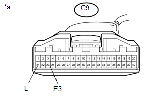
*a |
Front view of wire harness connector (to Combination Meter Assembly) |
| OK | |
REPLACE COMBINATION METER ASSEMBLY |
|
|
3. |
CHECK HARNESS AND CONNECTOR (COMBINATION METER ASSEMBLY - FUEL SUCTION WITH PUMP AND GAUGE TUBE ASSEMBLY) |
(a) Disconnect the C9 combination meter assembly connector.
(b) Disconnect the F19 (for 2TR-FE) or F44 (2GR-FKS) fuel suction with pump and gauge tube assembly connector.
(c) Measure the resistance according to the value(s) in the table below.
Standard Resistance (for 2TR-FE):
|
Tester Connection |
Condition |
Specified Condition |
|---|---|---|
|
C9-21 (L) - F19-2 |
Always |
Below 1 Ω |
|
C9-21 (L) or F19-2 - Body ground |
Always |
10 kΩ or higher |
|
C9-23 (E3) - F19-3 |
Always |
Below 1 Ω |
|
C9-23 (E3) or F19-3 - Body ground |
Always |
10 kΩ or higher |
Standard Resistance (for 2GR-FKS):
|
Tester Connection |
Condition |
Specified Condition |
|---|---|---|
|
C9-21 (L) - F44-2 |
Always |
Below 1 Ω |
|
C9-21 (L) or F44-2 - Body ground |
Always |
10 kΩ or higher |
|
C9-23 (E3) - F44-3 |
Always |
Below 1 Ω |
|
C9-23 (E3) or F44-3 - Body ground |
Always |
10 kΩ or higher |
| NG | |
REPAIR OR REPLACE HARNESS OR CONNECTOR |
|
|
4. |
INSPECT FUEL SENDER GAUGE ASSEMBLY |
(a) Remove the fuel sender gauge assembly.
- for 2TR-FE: (See page
.gif) )
) - for 2GR-FKS: (See page )
(b) Inspect the fuel sender gauge assembly.
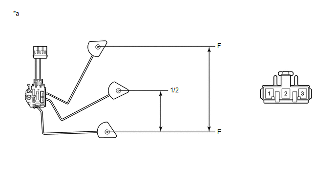 Text in Illustration
|
*a |
Component without harness connected (Fuel Sender Gauge Assembly) |
- |
- |
(c) Measure the resistance according to the value(s) in the table below.
Standard Resistance:
for: 2TR-FE|
Tester Connection |
Float Level |
Float Position (mm (in.)) |
Specified Condition |
|---|---|---|---|
|
1 - 2 |
F |
181.9 to 193.9 (7.161 to 7.633) |
3.0 to 5.0 Ω |
|
1/2 |
90.9 to 102.9 (3.578 to 4.051) |
55.6 to 62.4 Ω |
|
|
E |
0 (0) |
109.0 to 111.0 Ω |
|
Tester Connection |
Float Level |
Float Position (mm (in.)) |
Specified Condition |
|---|---|---|---|
|
1 - 2 |
F |
181.9 to 193.9 (7.161 to 7.633) |
13.5 to 16.5 Ω |
|
1/2 |
90.9 to 102.9 (3.578 to 4.051) |
201.0 to 224.0 Ω |
|
|
E |
0 (0) |
405.5 to 414.5 Ω |
|
Result |
Proceed to |
|---|---|
|
OK |
A |
|
NG (for 2TR-FE) |
B |
|
NG (for 2GR-FKS) |
C |
| B | |
REPLACE FUEL SENDER GAUGE ASSEMBLY (for 2TR-FE) |
| C | |
REPLACE FUEL SENDER GAUGE ASSEMBLY (for 2GR-FKS) |
|
|
5. |
INSPECT FUEL SUCTION PUMP AND GAUGE TUBE ASSEMBLY |
|
(a) Remove the fuel suction pump and gauge tube assembly.
|
|
(b) Measure the resistance according to the value(s) in the table below.
Standard Resistance:
|
Tester Connection |
Condition |
Specified Condition |
|---|---|---|
|
A-2 - B-2 |
Always |
Below 1 Ω |
|
A-3 - B-1 |
|
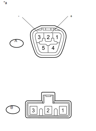
*a |
Component without harness connected (Fuel Suction with Pump and Gauge Tube Assembly) |
|
Result |
Proceed to |
|---|---|
|
OK |
A |
|
NG (for 2TR-FE) |
B |
|
NG (for 2GR-FKS) |
C |
| A | |
REPLACE COMBINATION METER ASSEMBLY |
| B | |
REPLACE FUEL SUCTION WITH PUMP AND GAUGE TUBE ASSEMBLY (for 2TR-FE) |
| C | |
REPLACE FUEL SUCTION W/PUMP & GAUGE TUBE ASSEMBLY (for 2GR-FKS) |
 On-vehicle Inspection
ON-VEHICLE INSPECTION
PROCEDURE
1. INSPECT SPEEDOMETER
(a) Check speedometer operation.
NOTICE:
The meter ECU receives the vehicle speed signal from the skid control
ECU via CAN commu ...
 Open in Turn Signal Circuit (B1507,B1508)
DESCRIPTION
This DTC is stored when the combination meter assembly detects an open in a turn
signal light circuit, a short in a turn signal light circuit, or a short in the
hazard warning light c ...
Other materials:
Short in Curtain Shield Squib RH Circuit (B1830/57-B1833/57)
DESCRIPTION
The front passenger side curtain shield squib circuit consists of the airbag
sensor assembly and the curtain shield airbag assembly RH.
The circuit signals the SRS to deploy when airbag deployment conditions are met.
These DTCs are set when a malfunction is detected in the front pas ...
Removal
REMOVAL
CAUTION / NOTICE / HINT
HINT:
Use the same procedure for the RH side and LH side.
The following procedure is for the LH side.
PROCEDURE
1. PRECAUTION
NOTICE:
After turning the ignition switch off, waiting time may be required before disconnecting
the cable from the ...
Precaution
PRECAUTION
1. IGNITION SWITCH EXPRESSION
(a) The type of ignition switch used on this model differs depending on the specifications
of the vehicle.
The expressions listed in the table below are used in this section.
Expression
Ignition Switch (Position)
Engine ...
