Toyota Tacoma (2015-2018) Service Manual: Open in Bus 2 Main Bus Line
DESCRIPTION
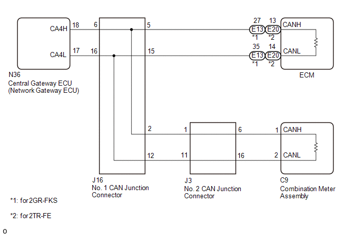
There may be an open circuit in one of the CAN main bus lines and/or a central gateway ECU (network gateway ECU) branch lines when the resistance between terminals 18 (CA4H) and 17 (CA4L) of the central gateway ECU (network gateway ECU) is 70 Ω or higher.
|
Detection Item |
Trouble Area |
|---|---|
|
Resistance between terminals 18 (CA4H) and 17 (CA4L) of central gateway ECU (network gateway ECU) is 70 Ω or higher. |
|
This malfunction is not related to the lines of a CAN branch except the central gateway ECU (network gateway ECU) branch lines or to ECUs or sensors connected to a CAN branch.
WIRING DIAGRAM
CAUTION / NOTICE / HINT
CAUTION:
When performing the confirmation driving pattern, obey all speed limits and traffic laws.
NOTICE:
- Because the order of diagnosis is important to allow correct diagnosis,
make sure to begin troubleshooting using How to Proceed with Troubleshooting
when CAN communication system related DTCs are output.
Click here
.gif)
- Before measuring the resistance of the CAN bus, turn the ignition switch off and leave the vehicle for 1 minute or more without operating the key or any switches, or opening or closing the doors. After that, disconnect the cable from the negative (-) battery terminal and leave the vehicle for 1 minute or more before measuring the resistance.
- After turning the ignition switch off, waiting time may be required
before disconnecting the cable from the negative (-) battery terminal. Therefore,
make sure to read the disconnecting the cable from the negative (-) battery
terminal notices before proceeding with work.
Click here
- Some parts must be initialized and set when replacing or removing and
installing parts.
Click here
- After performing repairs, perform the DTC check procedure and confirm
that the DTCs are not output again.
DTC check procedure: Turn the ignition switch to ON and wait for 1 minute or more. Then operate the suspected malfunctioning system and drive the vehicle at 60 km/h (37 mph) or more for 5 minutes or more.
- After the repair, perform the CAN bus check and check that all the ECUs
and sensors connected to the CAN communication system are displayed as normal.
Click here
HINT:
- Before disconnecting related connectors for inspection, push in on each connector body to check that the connector is not loose or disconnected.
- When a connector is disconnected, check that the terminals and connector body are not cracked, deformed or corroded.
PROCEDURE
|
1. |
CHECK FOR OPEN IN CAN BUS LINES (CENTRAL GATEWAY ECU (NETWORK GATEWAY ECU)) |
(a) Disconnect the cable from the negative (-) battery terminal.
|
(b) Disconnect the central gateway ECU (network gateway ECU) connector. |
|
(c) Measure the resistance according to the value(s) in the table below.
Standard Resistance:
|
Tester Connection |
Condition |
Specified Condition |
|---|---|---|
|
N36-18 (CA4H) - N36-17 (CA4L) |
Cable disconnected from negative (-) battery terminal |
108 to 132 Ω |
|
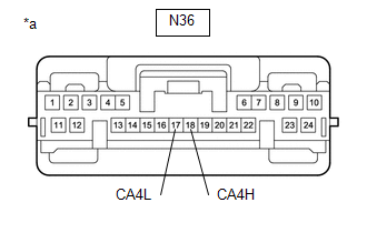
*a |
Front view of wire harness connector (to Central Gateway ECU (Network Gateway ECU)) |
| OK | .gif) |
REPLACE CENTRAL GATEWAY ECU (NETWORK GATEWAY ECU) |
|
.gif)
|
2. |
CHECK FOR OPEN IN CAN BUS LINES (COMBINATION METER ASSEMBLY) |
(a) Reconnect the N36 central gateway ECU (network gateway ECU) connector.
|
(b) Disconnect the combination meter assembly connector. |
|
(c) Measure the resistance according to the value(s) in the table below.
Standard Resistance:
|
Tester Connection |
Condition |
Specified Condition |
|---|---|---|
|
C9-1 (CANH) - C9-2 (CANL) |
Cable disconnected from negative (-) battery terminal |
108 to 132 Ω |
|
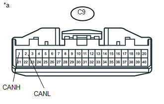
*a |
Front view of wire harness connector (to Combination Meter Assembly) |
| OK | |
REPLACE COMBINATION METER ASSEMBLY |
|
|
3. |
CHECK FOR OPEN IN CAN BUS LINES (ECM) |
(a) for 2GR-FKS
(1) Reconnect the C9 combination meter assembly connector.
|
(2) Disconnect the ECM connector. |
|
(3) Measure the resistance according to the value(s) in the table below.
Standard Resistance:
|
Tester Connection |
Condition |
Specified Condition |
|---|---|---|
|
E13-27 (CANH) - E13-35 (CANL) |
Cable disconnected from negative (-) battery terminal |
108 to 132 Ω |
|
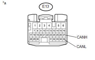
*a |
Front view of wire harness connector (to ECM) |
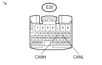
(b) for 2TR-FE
(1) Reconnect the C9 combination meter assembly connector.
|
(2) Disconnect the ECM connector. |
|
(3) Measure the resistance according to the value(s) in the table below.
Standard Resistance:
|
Tester Connection |
Condition |
Specified Condition |
|---|---|---|
|
E20-13 (CANH) - E20-14 (CANL) |
Cable disconnected from negative (-) battery terminal |
108 to 132 Ω |
|
*a |
Front view of wire harness connector (to ECM) |
|
Result |
Proceed to |
|---|---|
|
OK (for 2GR-FKS) |
A |
|
OK (for 2TR-FE) |
B |
|
NG |
C |
| A | |
REPLACE ECM |
| B | |
REPLACE ECM |
|
|
4. |
CHECK FOR OPEN IN CAN BUS LINES (NO. 1 CAN JUNCTION CONNECTOR) |
(a) Reconnect the E13*1 or E20*2 ECM connector.
- *1: for 2GR-FKS
- *2: for 2TR-FE
|
(b) Disconnect the No. 1 CAN junction connector. |
|
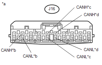
(c) Measure the resistance according to the value(s) in the table below.
Standard Resistance:
|
Tester Connection |
Condition |
Specified Condition |
Connect to |
|---|---|---|---|
|
J16-2 (CANH) - J16-12 (CANL) |
Cable disconnected from negative (-) battery terminal |
108 to 132 Ω |
No. 2 CAN junction connector |
|
J16-5 (CANH) - J16-15 (CANL) |
Cable disconnected from negative (-) battery terminal |
108 to 132 Ω |
ECM |
|
J16-6 (CANH) - J16-16 (CANL) |
Cable disconnected from negative (-) battery terminal |
54 to 69 Ω |
Central gateway ECU (network gateway ECU) |
|
*a |
Front view of wire harness connector (to No. 1 CAN Junction Connector) |
|
*b |
to No. 2 CAN Junction Connector |
|
*c |
to ECM |
|
*d |
to Central Gateway ECU (Network Gateway ECU) |
|
Result |
Proceed to |
|---|---|
|
OK |
A |
|
NG (ECM CAN main line) |
B |
|
NG (Central Gateway ECU (Network Gateway ECU) CAN branch line) |
C |
|
NG (No. 2 CAN junction connector CAN main line) |
D |
| A | |
REPLACE NO. 1 CAN JUNCTION CONNECTOR |
| B | |
REPAIR OR REPLACE CAN MAIN LINE OR CONNECTOR (NO. 1 CAN JUNCTION CONNECTOR - ECM) |
| C | |
REPAIR OR REPLACE CAN BRANCH LINE OR CONNECTOR (NO. 1 CAN JUNCTION CONNECTOR - CENTRAL GATEWAY ECU (NETWORK GATEWAY ECU)) |
|
|
5. |
CHECK FOR OPEN IN CAN BUS LINES (NO. 2 CAN JUNCTION CONNECTOR) |
(a) Reconnect the J16 No. 1 CAN junction connector.
|
(b) Disconnect the No. 2 CAN junction connector. |
|
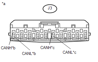
(c) Measure the resistance according to the value(s) in the table below.
Standard Resistance:
|
Tester Connection |
Condition |
Specified Condition |
Connect to |
|---|---|---|---|
|
J3-1 (CANH) - J3-11 (CANL) |
Cable disconnected from negative (-) battery terminal |
108 to 132 Ω |
No. 1 CAN junction connector |
|
J3-6 (CANH) - J3-16 (CANL) |
Cable disconnected from negative (-) battery terminal |
108 to 132 Ω |
Combination meter assembly |
|
*a |
Front view of wire harness connector (to No. 2 CAN Junction Connector) |
|
*b |
to No. 1 CAN Junction Connector |
|
*c |
to Combination Meter Assembly |
|
Result |
Proceed to |
|---|---|
|
OK |
A |
|
NG (Combination meter assembly CAN main line) |
B |
|
NG (No. 1 CAN junction connector CAN main line) |
C |
| A | |
REPLACE NO. 2 CAN JUNCTION CONNECTOR |
| B | |
REPAIR OR REPLACE CAN MAIN LINE OR CONNECTOR (NO. 2 CAN JUNCTION CONNECTOR - COMBINATION METER ASSEMBLY) |
| C | |
REPAIR OR REPLACE CAN MAIN LINE OR CONNECTOR (NO. 2 CAN JUNCTION CONNECTOR - NO. 1 CAN JUNCTION CONNECTOR) |
 Navigation Receiver Assembly Communication Stop Mode
DESCRIPTION
Detection Item
Symptom
Trouble Area
Navigation Receiver Assembly Communication Stop Mode
Either condition is met:
...
 Check Bus 2 Line for Short to +B
DESCRIPTION
There may be a short circuit between one of the CAN bus lines and +B when no
resistance exists between terminal 18 (CA4H) of the central gateway ECU (network
gateway ECU) and terminal ...
Other materials:
Terminals Of Ecm
TERMINALS OF ECM
1. ECM
HINT:
The standard voltage between each pair of ECM terminals is shown in the table
below. In the table, first follow the information under "Condition". Look under
"Terminal No. (Symbol)" for the terminals to be inspected. The standard voltage
b ...
Main Owners Manual
Please note that this manual applies to all models explains and all equipment,
including options. Therefore, you may find some explanations for equipment not installed
on your vehicle.
All specifications provided in this manual are current at the time of printing.
However, because of the Toyot ...
Inspection
INSPECTION
PROCEDURE
1. INSPECT FUEL INJECTOR ASSEMBLY
(a) Measure the resistance according to the value(s) in the table below.
Standard Resistance:
Tester Connection
Condition
Specified Condition
1 - 2
20°C (68°F)
11.6 ...
